Zabg6002 – Diodes ZABG6002 User Manual
Page 8
ZABG6002
ZABG6002
Document number: DS32078 Rev. 1 - 2
8 of 12
May 2010
© Diodes Incorporated
A Product Line of
Diodes Incorporated
This allows the optimization of drain currents for differing tasks such as input stages where noise can be critical and
later amplifier stages where gain may be more important. A graph showing the relationship between the value of
R
CAL
and I
D
is provided in the Typical Characteristics section of this datasheet. To ensure that the mixer function is
disabled the R
CAL
M pin should be left open circuit.
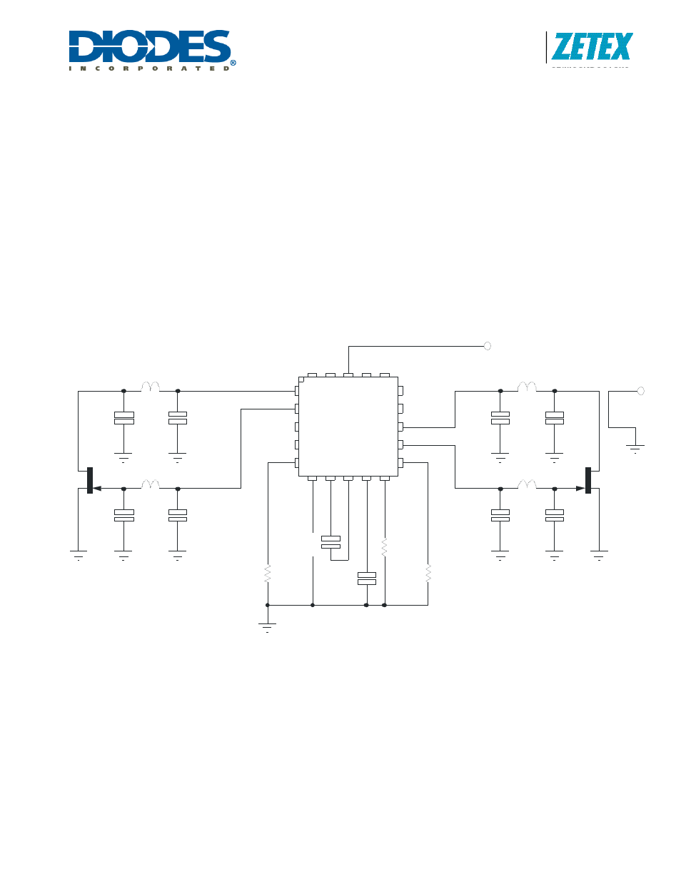
ZABG6002 in 4 LNA and 2 active mixer mode
Below is a partial applications circuit for the ZABG6002 showing all external components needed for biasing one of
the four FET stages available for LNA bias and one of the two mixer bias stages. Each LNA bias stage is provided
with a gate and drain pin. The drain pin provides a regulated 2.0V supply that includes a drain current monitor. Each
mixer bias stage is provided with a gate and drain pin. The drain pin provides a regulated 0.3V supply that includes
a drain current monitor but optimized to the requirements of an active mixer. The drain current taken by the external
FET (LNA and Mixer) is compared with a user selected level, generating a signal that adjusts the gate voltage of the
FET to obtain the required drain current. If for any reason, an attempt is made to draw more than the user set drain
current from the drain pin, the drain voltage will be reduced to ensure excess current is not taken. The gate pin
drivers are also current limited.
JF2
Vcc
L*
L*
C*
C*
C1
10nF
C2
10nF
CNB
47nF
CSUB
47nF
RCAL2
36k
* Stripline Elements
RCAL1
36k
G2
Gn
d
D3
G3
Cn
b
1
G1
D4
Vc
c
D1
D5
D2
G5
Cn
b
2
Cs
u
b
D6
G6
Rc
a
l2
Rcal1
RcalM
G4
ZABG6002
RCALM
68k
JFM
L*
L*
C*
C*
C3
10nF
C4
10nF
VLO
The bias stages are split up into three groups, with the drain current of each group set by an external R
CAL
resistor.
R
CAL
1 sets the LNA drain currents of stages 1 and 4 and R
CAL
2 sets the drain currents of LNA stages 2 and 5. R
CALM
sets the mixer drain currents of stages 3 and 6. This allows the optimization of drain currents for differing tasks such
as input stages where noise can be critical and later amplifier stages where gain may be more important. A graph
showing the relationship between the value of R
CAL
and I
D
is provided in the Typical Characteristics section of this
datasheet.