Pilz PSS SB M12 TERMINATOR User Manual
Page 2
- 2 -
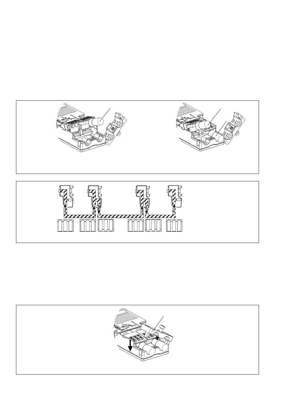
Abschlussstecker (Fig. 3 a):
Busanfang/Busende - Abschlussstecker
konfektionieren! (siehe Fig. 4 a)
➀
Ankommendes Buskabel einlegen: Der
Pfeil für die Einlegerichtung zeigt nach
innen.
Anschlussstecker (Fig. 3 b):
Verbindung von zwei Busteilnehmern -
Anschlussstecker konfektionieren! (siehe
Fig. 4 b)
Ankommendes und abgehendes Buskabel
einlegen:
➁
Ankommendes Kabel: Der Pfeil für die
Einlegerichtung zeigt nach innen.
➂
Abgehendes Kabel: Der Pfeil für die
Einlegerichtung zeigt nach außen.
Kabeladern fixieren
Beachten:
• Der Kabelschirm muss blank auf der
Metallführung liegen.
• Es sind max. 10 Kontaktierzyklen der
Schneidklemmen möglich.
➀
Kontaktierklemmen schließen (Fig. 5)
Die Einzelleiter werden in die Schneid-
klemmen gedrückt.
➁
Zugentlastung schließen und festschrau-
ben.
Terminator (Fig. 3 a):
Start of the bus/end of the bus - configure
terminator! (see Fig. 4 a)
➀
Insert IN bus cable: The arrow indicating
the insertion direction points to the inside.
Plug (Fig. 3 b):
Connection of two bus subscribers -
configure plug! (see Fig. 4 b)
Insert IN and OUT bus cable:
➁
IN cable: The arrow indicating the
insertion direction points to the inside.
➁
OUT cable: The arrow indicating the
insertion direction points to the outside.
Fixing single strands
Note:
• The screening must be bare on the metal
rail.
• The IDC connections can have a max. of
10 contact cycles.
➀
Close clamped connectors (Fig. 5)
The single strands are pressed into the
IDC connections.
➁
Close and attach screws of the strain
relief.
Fiche de terminaison (fig. 3 a) :
Confectionner des fiches de terminaison
pour le début et la fin du bus ! (voir fig. 4 a)
➀
Mettre en place le câble de bus entrant :
la flèche indiquant le sens de pose est
orientée vers l’intérieur.
Fiche de connexion (fig. 3 b) :
Confectionner une fiche de connexion pour
raccorder deux abonnés ! (voir fig. 4 b)
Mettre en place les câbles de bus entrant et
sortant :
➁
Câble entrant : la flèche indiquant le sens
de pose est orientée vers l’intérieur.
➂
Câble sortant : la flèche indiquant le sens
de pose est orientée vers l’extérieur.
Fixer les fils du câble
Attention :
• La partie du câble de blindage en contact
avec le guidage métallique doit être
dénudée.
• Un maximum de 10 cycles de contacts
des bornes guillotine est possible.
➀
Fermer les bornes de contact (fig. 5)
Les conducteurs sont pressés dans la
borne guillotine.
➁
Fermer et visser le délestage de traction.
CAN
- HIGH
CAN
- GND
CAN
- LOW
CAN
- LOW
CAN
- GND
CAN
- HIGH
CAN
- HIGH
CAN
- GND
CAN
- LOW
CAN
- LOW
CAN
- GND
CAN
- HIGH
R
CAN
- HIGH
CAN
- GND
CAN
- LOW
R
CAN
- HIGH
CAN
- GND
CAN
- LOW
Fig. 4: An-/Abschlussstecker konfektionieren/Configuring plugs/terminators/Confectionner une fiche de raccordement/terminaison
b
a
b
a
a
➀
Fig. 3: Kabel einlegen bei der Konfektionierung von Abschlussstecker und Anschlussstecker/Inserting the cable when configuring the
terminator and plug/Mettre en place le câble de raccordement pour la confection de la fiche de terminaison et la fiche de
connexion
b
➁
➂
Fig. 5: Kabeladern fixieren/Fixing single strands/Fixer les fils du câble
➀
➁