6 wiring, 1 general wiring guidelines, 1 mechanical connection of the base modules – Pilz PSSu E F PS2 User Manual
Page 19: Section 6, Wiring, General wiring guidelines, Mechanical connection of the base modules, 6wiring, Din 5264-a
Wiring
Operating Manual PSSu E F PS2(T)(R)
1002237EN03
19
6
Wiring
6.1
General wiring guidelines
Please note:
}
The requirements of the supply voltages can be found in the chapter entitled "Technical
Details".
}
Protective separation must be ensured for the external power supplies that generate
the supply voltages. Failure to do so could result in electric shock.
}
The external power supplies must comply with the current applicable standard EN
609501, EN 61140, EN 50178 or EN 615581.
}
The maximum current load for the periphery supply on the module bus is 10 A. Please
refer to the derating diagram in the chapter entitled "Function Description".
}
Earth the 0 V supply on the periphery supply or monitor each supply group for earth
faults.
}
The connection of the 0 V supply to the central earth bar or earth fault monitor must be
in accordance with relevant national regulations (e.g. EN 602041, NFPA 79:177,
NEC: Article 250).
}
Details of the minimum range for conductor cross sections on connection terminals can
be found in the section entitled "Technical Details".
}
Use copper wiring.
6.1.1
Mechanical connection of the base modules
Procedure:
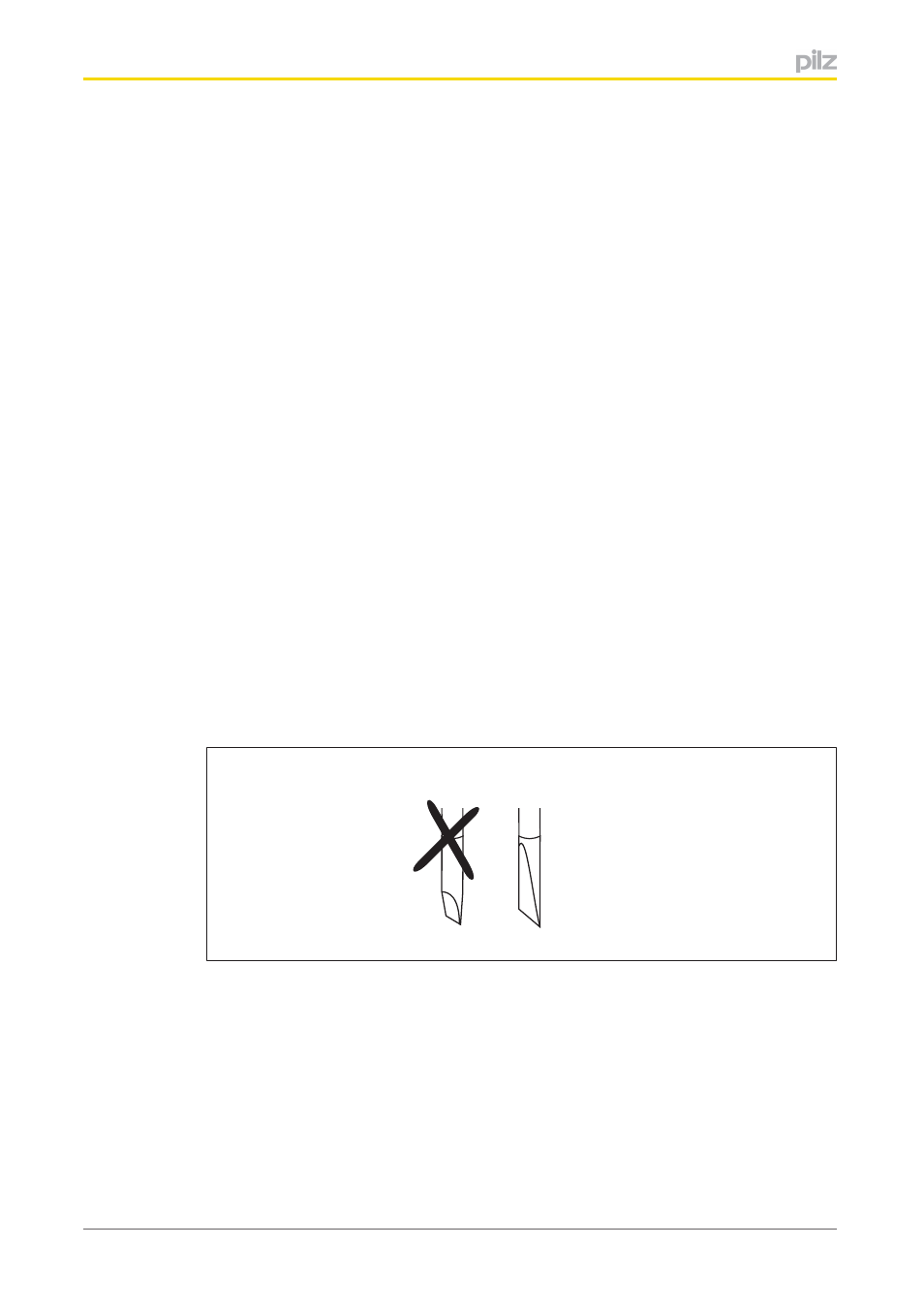
}
Use a flat blade screwdriver (DIN 5264A)!
DIN 5264-A
}
Strip the wire back 8 mm.
}
If necessary, label the connection level with a colour marker [3].
}
Base module with screw terminals:
–
Use a screwdriver to loosen the screw on the screw terminal [1]
–
Insert the stripped cable into the round fixing hole [2], as far as it will go.
–
Tighten up the screw on the screw terminal.
–
Check that the cable is firmly seated.