Nexen BD 933507 User Manual
Page 18
18
FORM NO. L-20063-AD-0314
5. Remove the Shoe Pins (Item 16) from the Arms (Item
2), Friction Facings (Item 4), and Shoes (Item 3) (See
Figure 17).
6. Slide the Friction Facings (Item 4) and Shoes (Item 3)
off of the Arms (Item 2) (See Figure 17).
7. Remove the four Cap Screws (Item 24) securing the
Pivot Pin Retainer Plate (Item 6) (See Figure 17).
8. Remove the Pivot Pin Retainer Plate (Item 6) (See
Figure 17).
9. Press the Pivot Pins (Item 7) out of the BD Caliper
Brake (See Figure 17).
10. Slide Arms (Item 2) out of Main Frame (Item 1) (See
Figure 17).
1. Loosen the Spanner Nut (Item 12) (See Figure 17).
2. Remove the Adjustment Screw (Item 8) and the Spanner
Nut (Item 12) from the Arm (Item 2) (See Figure 16).
3. Remove the Actuator (Item 11) from the other Arm
(Item 2) (See Figure 17).
4. Remove the Return Springs (Item 17) and Spring
Retainers (Item 5) from the Arms (Item 2) (See Figure
17).
HIGH PV BEARINGS (ITEMS 14 AND 15)
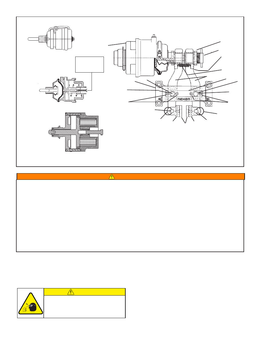
FIGURE 17
12
8
11
2
17
5
16
16
4
3
3
24
24
6
7
14
7
14
1
15
15
Tap Bolt
located under
Breather Cap.
Two-Port
Actuator
Three-Port
Actuator
60 PSI
Actuator
CAUTION
Working with spring loaded or tension
loaded fasteners and devices can cause
injury. Wear safety glasses and take the
appropriate safety precautions.
WARNING
Spring actuated brakes must be manually released prior to brake disassembly.
o
BSolete
t
hree
-P
ort
a
ctuator
Apply hold-off air pressure to remove tension on the Tap Bolt and use a 9/16 inch socket wrench to turn the Tap Bolt
counterclockwise until the brake is released (approximately forty turns).
t
wo
-P
ort
a
ctuator
Apply hold off pressure to remove tension on the Tap Bolt and use a 3/4 inch socket wrench to turn the Tap Bolt counterclockwise
to fully cage (compress) the spring. The spring is fully compressed when the bolt is backed out of the unit 21 mm [0.83 in].
60 PSi a
ctuator
Using a 15/16 inch socket, turn the manual release bolt clockwise until snug to fully cage (compress) the spring.
Hold-off air pressure can be removed at this time, and service performed (See Figure 15 a & b).
WARNING