Installation, Caution – Nexen BD 933507 User Manual
Page 6
6
FORM NO. L-20063-AD-0314
DISC
1. Thoroughly inspect the tapered bore of the disc hub
and the tapered surface of the Q.D. bushing. Remove
any dirt, grease, or foreign material from the disc hub
and Q.D. bushing. Do not use lubricants for this
installation.
2. Assemble the Q.D. bushing into the disc hub, aligning
the untapped holes in the bushing flange with the
tapped holes in the disc hub.
3. Insert the pull-up bolts and alternately and evenly tighten
them to the recommended torque (See Tables 1 and
2).
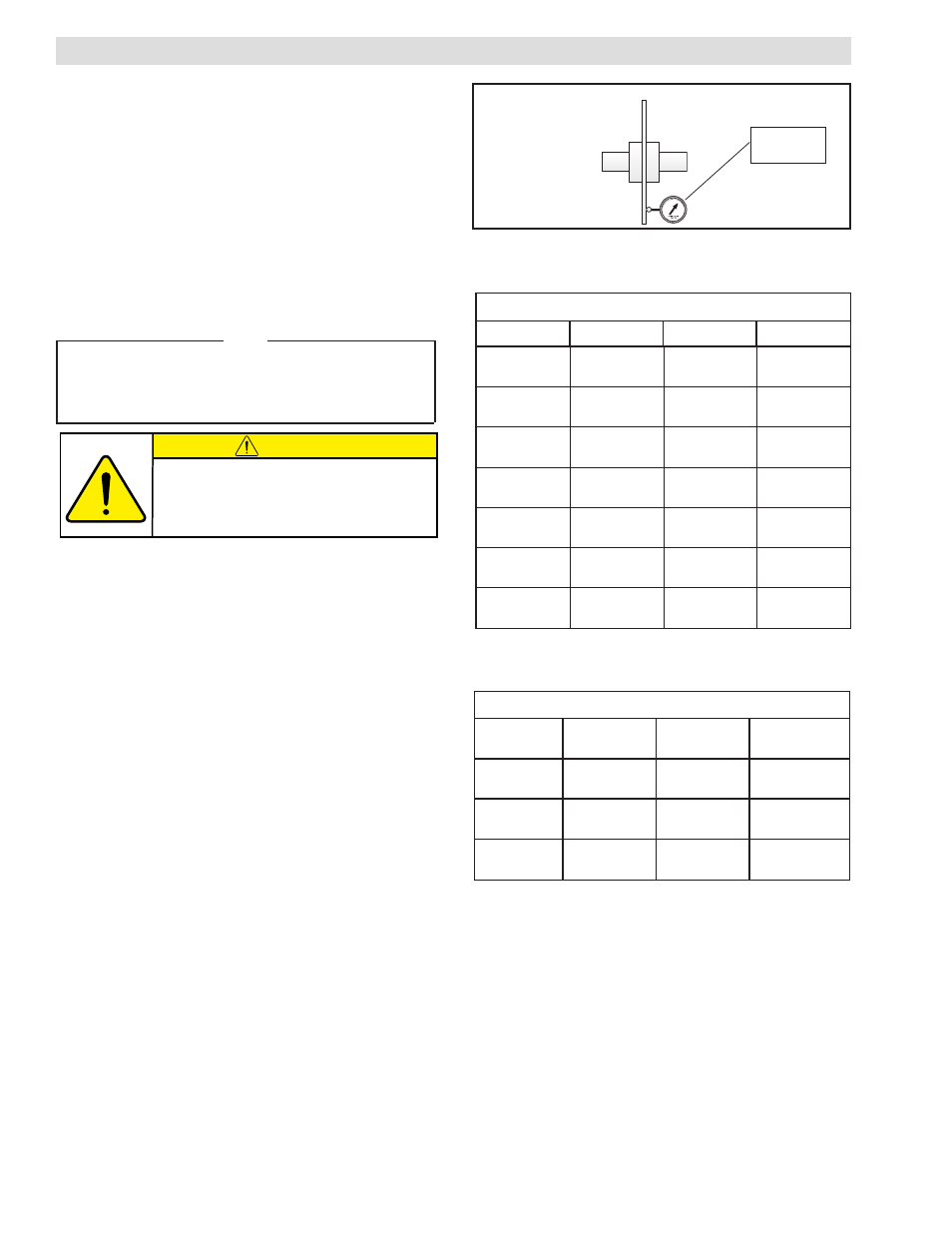
Note
Run-out is minimized if a Dial Indicator is used as the pull-up
bolts are tightened. Place the contact tip of the Dial Indicator
on the machined surface of the rotor to measure Run-out.
Run-out should be less than 3.8mm (.015 in) See Figure 1).
4. To remove the Q.D. bushing, remove the pull-up bolts
and reinsert into the threaded holes. Tighten the pull-
up bolts to push the disc hub off the Q.D. bushing.
INSTALLATION
Dial
Indicator
Figure 1
Table 1
Pull-up Bolt Torques For Non-Ventilated Discs
Table 2
Pull-up Bolt Torques For Ventilated Discs
S
E
U
Q
R
O
T
G
N
I
N
E
T
H
G
I
T
D
E
D
N
E
M
M
O
C
E
R
D
IAMETER
P
ART
N
UMBER
.
D
.
Q
B
USHING
T
ORQUE
m
m
5
0
3
]
n
i
2
1
[
1
0
2
4
3
9
F
S
m
N
5
.
0
4
]
b
l-
tf
0
3
[
m
m
6
5
3
]
n
i
4
1
[
2
0
2
4
3
9
E
m
N
1
8
]
b
l-
tf
0
6
[
m
m
6
0
4
]
n
i
6
1
[
3
0
2
4
3
9
E
m
N
1
8
]
b
l-
tf
0
6
[
m
m
7
5
4
]
n
i
8
1
[
4
0
2
4
3
9
J
m
N
5
.
2
8
1
b
l-
tf
3
3
1
m
m
8
0
5
]
n
i
0
2
[
5
0
2
4
3
9
J
m
N
5
.
2
8
1
b
l-
tf
3
3
1
m
m
9
5
5
]
n
i
2
2
[
6
0
2
4
3
9
J
m
N
5
.
2
8
1
b
l-
tf
3
3
1
0
1
6
]
n
i
4
2
[
7
0
2
4
3
9
J
m
N
5
.
2
8
1
b
l-
tf
3
3
1
S
E
U
Q
R
O
T
G
N
I
N
E
T
H
G
I
T
D
E
D
N
E
M
M
O
C
E
R
D
IAMETER
P
ART
N
UMBER
.
D
.
Q
B
USHING
T
ORQUE
m
m
5
.
3
6
4
]
n
i
5
2
.
8
1
[
0
0
2
4
3
9
J
m
N
5
.
2
8
1
]
b
l-
tf
5
3
1
[
m
m
3
3
5
]
n
i
1
2
[
0
0
3
4
3
9
J
m
N
5
.
2
8
1
]
b
l-
tf
5
3
1
[
m
m
0
1
6
]
n
i
4
2
[
0
0
4
4
3
9
J
m
N
5
.
2
8
1
]
b
l-
tf
5
3
1
[
CAUTION
If excessive tightening torque is applied, bursting
pressures are created in the hub. There must be
a gap between the flange of the Q.D. bushing
and the disc hub to ensure a proper press fit
of the Q.D. bushing onto the shaft.