Friction facing clearance adjustment, Warning – Nexen BD 933507 User Manual
Page 8
8
FORM NO. L-20063-AD-0314
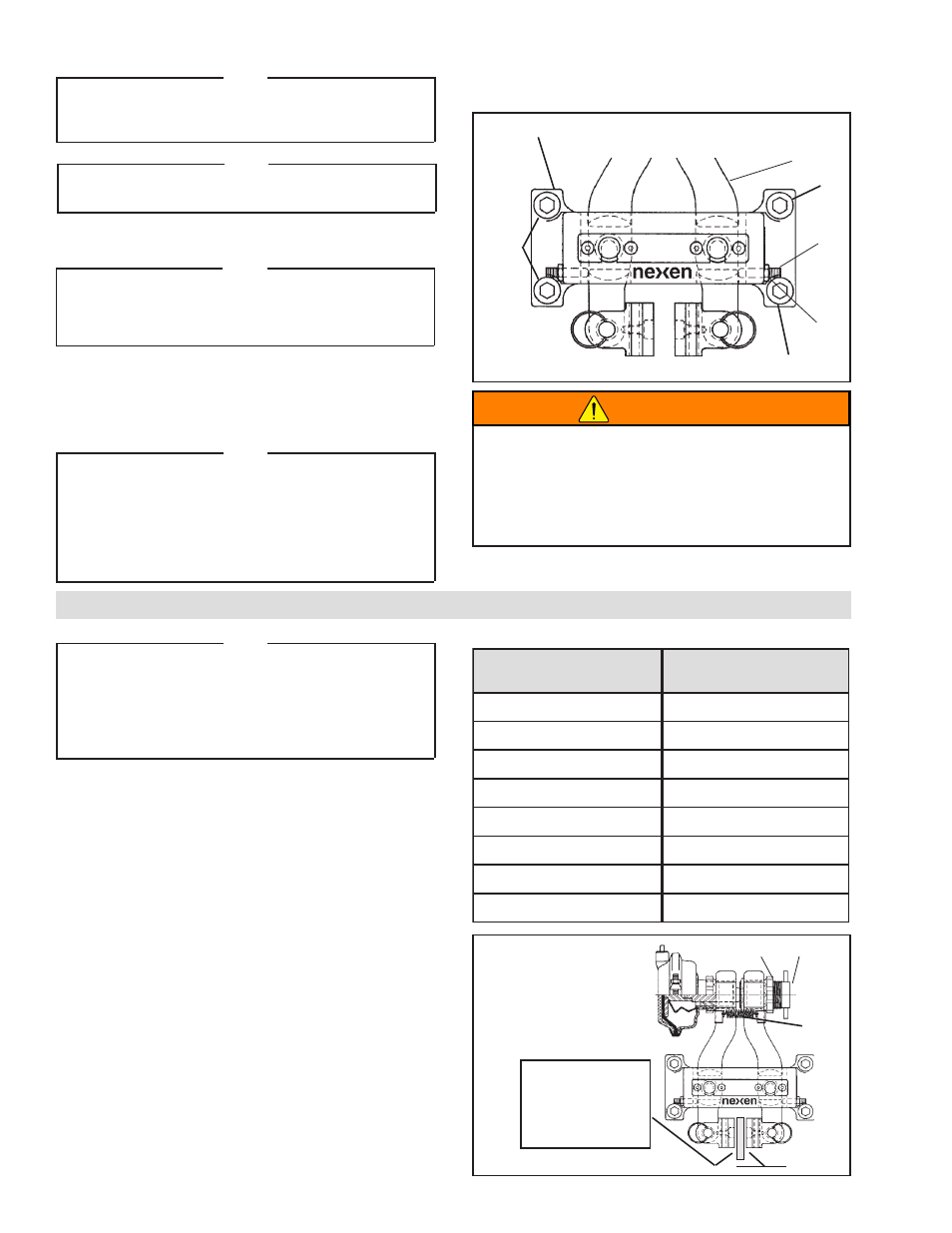
Figure 4
19
2
50
51
1
19
19
MAIN FRAME (MOUNTING BRAKE TO DISC)
NOTE
Set Screws (Item 50) and Nuts (Item 51) are provided to
hold Arms (Item 2) in place when the BD Caliper Brake is
used on vertical shaft installations (See Figure 4).
NOTE
If the BD Caliper Brake is spring engaged, release the brake
by applying 5.17-6.90 bar [75-100 psi] hold-off air pressure.
1. Locate the BD Caliper Brake in the desired position
in relation to the disc.
NOTE
If the BD Caliper Brake is air engaged, apply air to
the brake to lock it into position in relation to the
disc. If the BD Caliper is spring engaged, release the hold-
off air pressure.
2. Lock the BD Caliper Brake in position in relation to
the disc.
3. Align the customer supplied support with the Main
Frame (Item 1) mounting holes (See Figure 4).
Note
The support must be capable of sustaining loads produced
during braking.
If shims are used under the Main Frame (Item 1) mounting
pads, care must be taken to prevent warping of the Main
Frame when tightening the Cap Screws (Item 19) (See
Figure 4).
Note
For the Brakes listed in Table 3, the Friction Facing clearance
gap has been preset at the factory for the Friction Disc width
specified. The following adjustment process is necessary
only if the Friction Disc being used does not have the
same width as specified for the respective product that
is being installed.
Table 3
T
C
U
D
O
R
P
R
E
B
M
U
N
N
O
I
T
C
I
R
F
H
T
D
I
W
C
S
I
D
T
C
U
D
O
R
P
R
E
B
M
U
N
N
O
I
T
C
I
R
F
H
T
D
I
W
C
S
I
D
0
0
5
3
3
9
]
n
i
0
5
.
0
[
m
m
3
1
4
9
5
3
3
9
]
n
i
0
0
.
1
[
m
m
5
2
1
0
5
3
3
9
]
n
i
0
5
.
0
[
m
m
3
1
5
9
5
3
3
9
]
n
i
0
0
.
1
[
m
m
5
2
2
0
5
3
3
9
]
n
i
5
7
.
0
[
m
m
9
1
0
0
6
3
3
9
]
n
i
0
5
.
0
[
m
m
3
1
3
0
5
3
3
9
]
n
i
0
5
.
0
[
m
m
3
1
1
0
6
3
3
9
]
n
i
0
5
.
0
[
m
m
3
1
9
8
5
3
3
9
]
n
i
0
5
.
0
[
m
m
3
1
2
0
6
3
3
9
]
n
i
0
5
.
0
[
m
m
3
1
1
9
5
3
3
9
]
n
i
0
0
.
1
[
m
m
5
2
2
9
6
3
3
9
]
n
i
0
5
.
0
[
m
m
3
1
2
9
5
3
3
9
]
n
i
0
0
.
1
[
m
m
5
2
3
9
6
3
3
9
]
n
i
0
5
.
0
[
m
m
3
1
3
9
5
3
3
9
]
n
i
0
0
.
1
[
m
m
5
2
4
9
6
3
3
9
]
n
i
0
5
.
0
[
m
m
3
1
FRICTION FACING CLEARANCE ADJUSTMENT
4. Release the BD Caliper Brake from the disc.
5. Tighten the Cap Screws (Item 19) to 67.8 Nm [50
ft-lb] torque (See Figure 4).
AIR ACTUATED
1. Loosen adjustment screw Spanner Nut (Item 12)
(See Figure 5).
2. Loosen the Adjustment Screw (Item 8) until a 1/32
inch spacer can be slid between each of the Friction
Facings (Item 4) and Friction Disc (See Figure 5).
3. Turn the Adjustment Screw (Item 8) in until the
spacer can be just pulled out (See Figure 5).
4. Tighten the Spanner Nut (Item 12) to 13.6-20.3 Nm
[10-14 ft-lb] torque (See Figure 5).
Figure 5
12
8
1/32 inch spacer
between
Friction Facing
(Item 4)
and Friction Disc
17
WARNING
The Cap Screws (Item 19) must sustain the loads
produced by braking and preload produced by
mounting torque. The torque rating specified
above allows a significant load safety factor. Do
not over torque cap screws.
WARNING