Installation – Nexen Size 18 964102 User Manual
Page 2
2
FORM NO. L-20245-C-1099
INSTALLATION
GUIDE ROLL MECHANISM
1.
Position the Web Guide as close as possible to the
critical area to which the web is being guided. Any roll
between the lead out roll D and the critical area will
detract from guiding accuracy (See Figure 1).
2.
Find the web path to be used (See Figure 1).
a.
Lead in roll B and lead out roll D are customer
provided.
b.
The web must travel through the Web Guide in the
direction of the arrow on the Roll Base of the Web
Guide.
c.
Web lead in distance (B to A) and lead out distance
(C to D) must be at least equal to the web width.
NOTE
1
1
/
4
times the web width is the recommended distance
between web lead in and lead out.
d.
Ensure that the Web Guide roll A and C are parallel
to the web lead in roll B and the lead out roll D when
the Web Guide is in its mid-travel or centered
position.
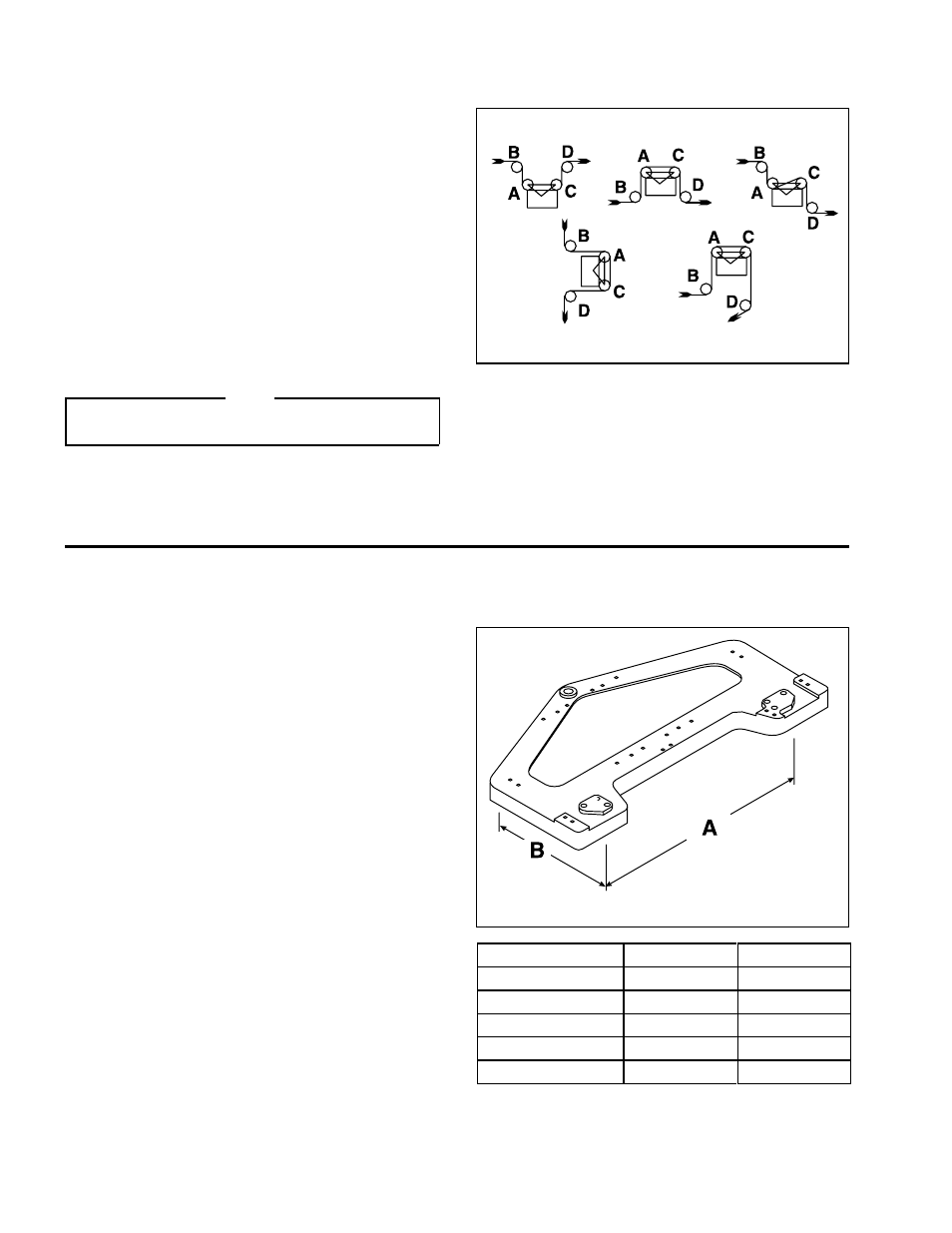
MOUNTING THE WEB GUIDE
Mount the Web Guide to the machine using the four M8 x
1.25 tapped mounting holes located on the underside of the
Base (See Figure 2 and Table 1 for mounting dimensions).
WEB GUIDE SIZE
A
B
18"
17.00"
7.50"
21"
15.75"
6.30"
24"
15.75"
6.30"
28"
27.00"
8.50"
32"
27.00"
9.50"
FIGURE 1
FIGURE 2
TABLE 1