Maintenance, Limit switch adjustment – Nexen Size 18 964102 User Manual
Page 7
7
FORM NO. L-20245-C-1099
9.
Set the Photo Head Selector Switch to RIGHT (See
Figure 8).
10. Loosen the right Knob and move the right Photo Head,
Bracket, and Sensor Bracket Mounting Block to the edge
of the web until the center green light on the Error
Indicator Array glows (See Figures 8 and 9); then,
tighten the Knob to secure the Photo Head.
11. Set the Photo Head Selector Switch to CENTER (See
Figure 8).
12. Set the Mode Switch to AUTO (See Figure 8).
13. Accelerate the machine. The web should remain centered
between the Photo Heads and the green light on the
Error Indicator Array should stay on.
14. If the web is misaligned with the centerline of the machine,
it can be moved with the Fine Adjustment Control located
on the control panel (plus or minus 0.20'' [5 mm]) (See
Figure 8).
15. If alignment errors still exist, repeat Steps 6 through 14.
MAINTENANCE
LIMIT SWITCH ADJUSTMENT
CAUTION
The Limit Switches have been set by Nexen for
maximum travel. Limit Switches must be adjusted to
interrupt movement before contact is made with a
physical obstruction or stop. Failure to do so will
damage the AE120 Controller. If there is no obstruction,
the Limit Switches should remain in their factory set
positions for maximum travel.
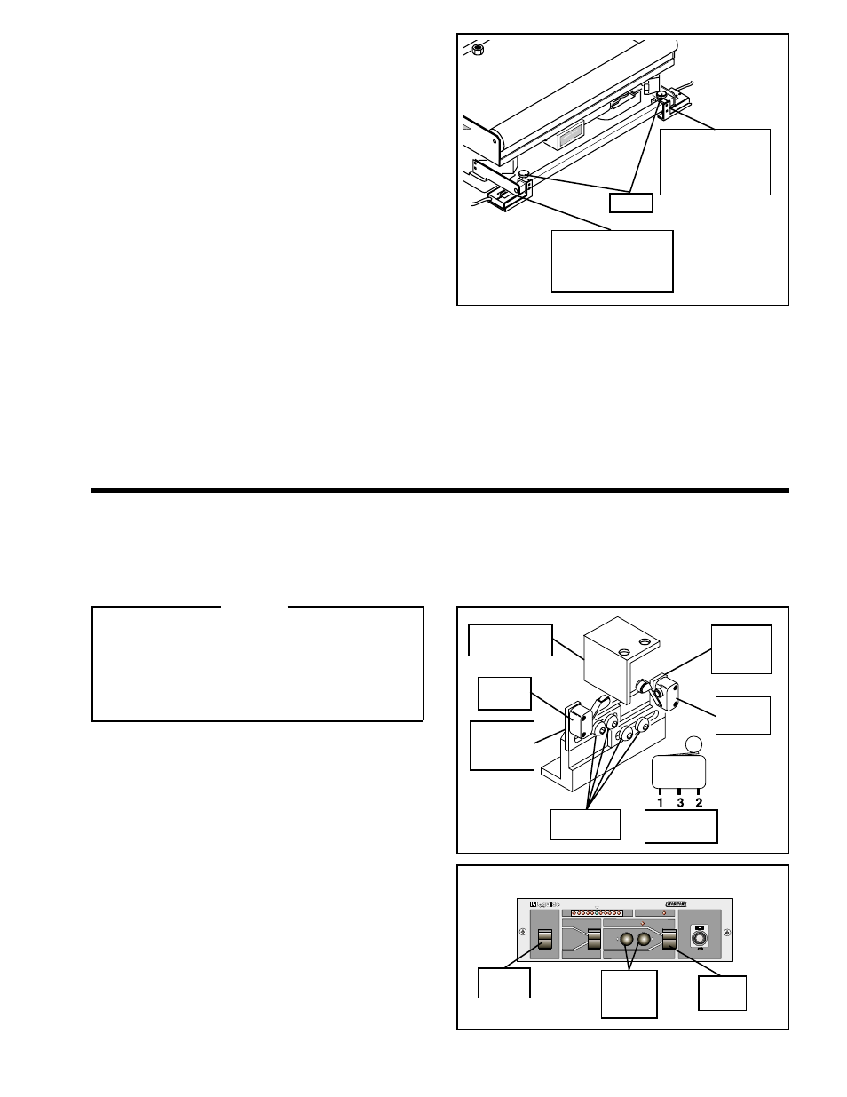
1.
Loosen the Pan Head Screws holding the Limit
Switch Brackets and slide the Limit Switch Brackets
and Limit Switches to their fully extended positions
(See Figure 10).
2.
Set the AE120 Power Switch to ON and the Mode Switch
to MAN (See Figure 11).
3.
Using the Manual Push Buttons located on the front
panel of the AE120, move the Limit Switch Stop Plate
(attached to the Roll Base) in one direction until the
desired end of travel is reached (See Figures 10 and 11).
4.
Connect a voltmeter across Terminals 1 and 2 of one
Limit Switch (See Figure 10).
5.
Slide the respective Limit Switch Bracket and Limit
Switch towards the Limit Switch Stop Plate until the Limit
Switch makes contact with the Limit Switch Stop Plate
and the voltmeter reads
±
5 volts.
MODEL
AE120
MAN
CENTER
AUTO
AUTO
POWER
ON
LEFT
CPC
RIGHT
MAN
Left Photo Head,
Bracket, and
Sensor Bracket
Mounting Block
Right Photo Head,
Bracket, and
Sensor Bracket
Mounting Block
Knob
FIGURE 9
FIGURE 10
Limit
Switch
Limit Switch
Stop Plate
Limit
Switch
Bracket
Pan Head
Screws
Limit
Switch
Limit
Switch
Bracket
Terminal
Locations
FIGURE 11
Power
Switch
Manual
Push
Buttons
Mode
Switch