Altpll ip core, Altpll ip core -5 – Altera MAX 10 Clocking and PLL User Manual
Page 43
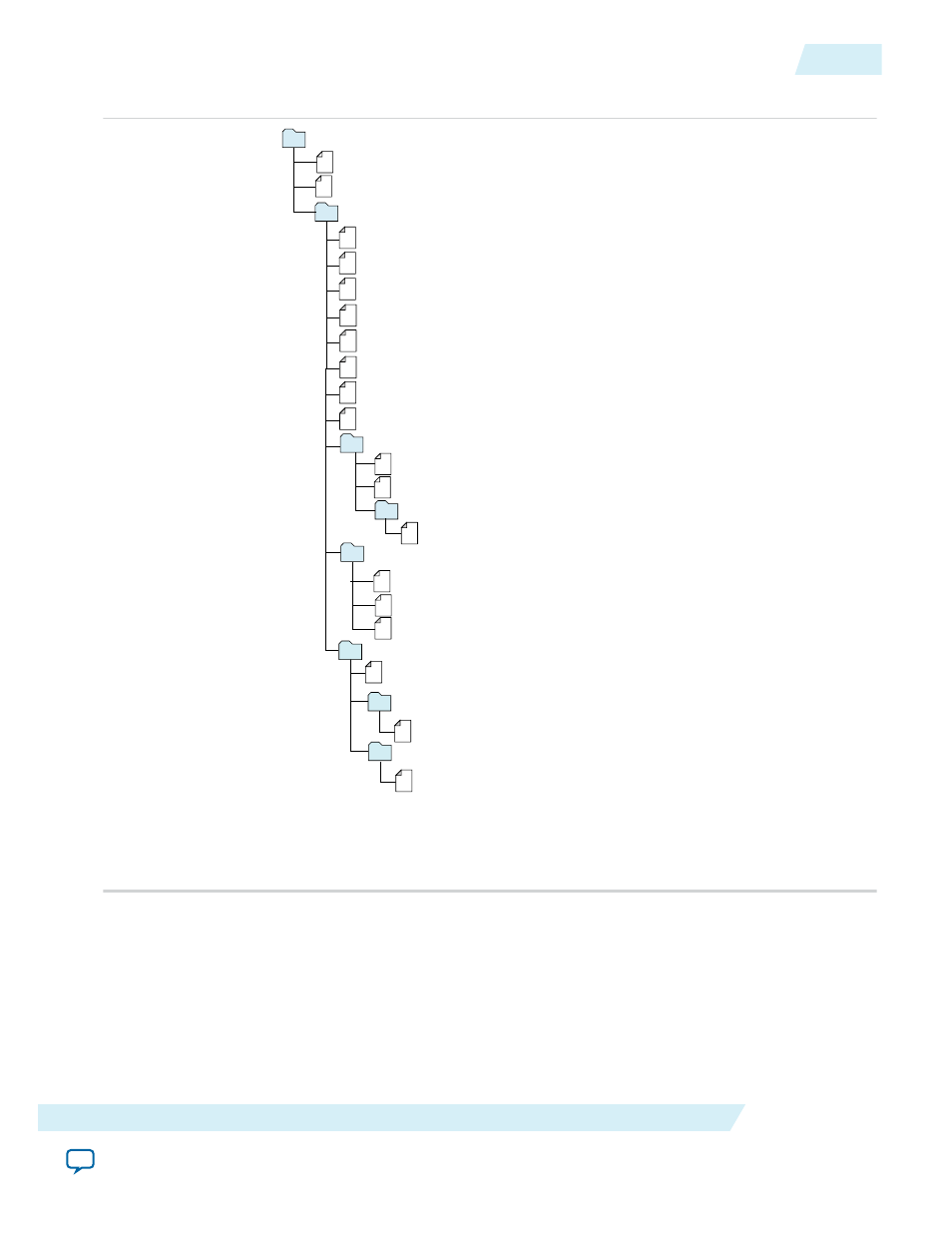
Figure 4-3: IP Core Generated Files
Notes:
1. If supported and enabled for your IP variation
2. If functional simulation models are generated
<Project Directory>
<your_ip>_bb.v - Verilog HDL black box EDA synthesis file
<your_ip>_inst.v or .vhd - Sample instantiation template
synthesis - IP synthesis files
<your_ip>.qip - Lists files for synthesis
testbench - Simulation testbench files
1
<testbench_hdl_files>
<simulator_vendor> - Testbench for supported simulators
<simulation_testbench_files>
<your_ip>.v or .vhd - Top-level IP variation synthesis file
simulation - IP simulation files
<your_ip>.sip - NativeLink simulation integration file
<simulator vendor> - Simulator setup scripts
<simulator_setup_scripts>
<your_ip> - IP core variation files
<your_ip>.qip or .qsys - System or IP integration file
<your_ip>_generation.rpt - IP generation report
<your_ip>.bsf - Block symbol schematic file
<your_ip>.ppf - XML I/O pin information file
<your_ip>.spd - Combines individual simulation startup scripts
1
<your_ip>.html - Contains memory map
<your_ip>.sopcinfo - Software tool-chain integration file
<your_ip>_syn.v or .vhd - Timing & resource estimation netlist 1
<your_ip>.debuginfo - Lists files for synthesis
<your_ip>.v, .vhd, .vo, .vho - HDL or IPFS models
2
<your_ip>_tb - Testbench for supported simulators
<your_ip>_tb.v or .vhd - Top-level HDL testbench file
ALTPLL IP Core
The ALTPLL IP core specifies the PLL circuitry. You can use this IP core to configure the PLL types,
operation modes, and advanced features of the PLL.
UG-M10CLKPLL
2015.05.04
ALTPLL IP Core
4-5
MAX 10 Clocking and PLL Implementation Guides
Altera Corporation