Altlvds_rx ip core – Altera POS-PHY Level 4 IP Core User Manual
Page 41
Chapter 4: Functional Description—Receiver
4–3
Block Description
December 2014
Altera Corporation
POS-PHY Level 4 IP Core User Guide
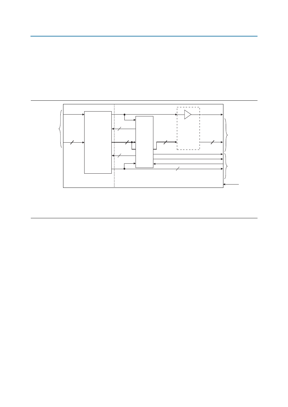
If the DPA parameter is turned on, the DPA feature consists of an ALTLVDS_RX IP
core with DPA enabled, and a channel aligner. For 64-bit data path width variations in
Stratix GX devices, this feature also consists of an 8:4 serializer (needed to achieve an
overall deserialization factor of 4). Three status signals: stat_rd_dpa_locked,
err_rd_dpa
and stat_rd_dpa_lvds_locked, and one control signal:
ctl_rd_dpa_force_unlock
are also part of this feature.
Figure 4–2
shows the DPA
block diagram.
ALTLVDS_RX IP Core
The ALTLVDS_RX IP core always performs deserialization on the input rdat and
rctl
high-speed LVDS signals, and divides the DDR rdclk to produce a slower
rdint_clk
.
When DPA is enabled in the POS-PHY Level 4 IP core, the ALTLVDS_RX IP core has
two other features enabled: DPA and bit slip. DPA with respect to ALTLVDS has a
different meaning than DPA with respect to the POS-PHY Level 4 IP core. After DPA
resets, the ALTLVDS DPA feature tolerates only a small amount of change to the
channel-to-channel skew, which compensates for the very small amounts of change in
channel-to-channel skew that may occur due to voltage and temperature shifts during
system operation. A change in channel-channel skew that is greater than the bit-time
tolerance causes one or more of the internal deskew FIFO buffers to underflow or
overflow, which the POS-PHY Level 4 IP core detects only as DIP-4 errors. You must
use the DIP-4 thresholds and stat_rd_dip4_oos to trigger the DPA reset by
asserting ctl_rd_dpa_force_unlock.
The stat_rd_dpa_lvds_locked signal indicates when the DPA cannot stay locked
either because of a lack of transitions on the channel, or because of rapid changes in
skew. The DPA run length is 6,400 UI for Stratix III, Stratix II, and Stratix GX devices.
If the traffic on the SPI-4.2 interface is very sparse, periodic training patterns may be
required.
Figure 4–2. DPA and Channel Aligner Block Diagram
Notes to
Figure 4–2
:
(1) The width of the data path for the data_out, data_out_algn, and data:2 signals depends on the deserialization factor.
(2) Exists only for Stratix GX devices, if the internal data path width is 64 bits.
(3) The stat_rd_dpa_lvds_locked signal does not exist in the altlvds block for Stratix GX devices. It is tied to a logic 1 inside the receiver IP core.
ALTLVDS_RX
Megafunction
(with DPA)
rx_data_phy_dpa
rdclk
rdat/rctl
Serial
Data
lvds_reset
16+1
align
16+1
data_out
128+/64+
data_out_algn
128+/64+
x2
PLL
clk x 2
data : 2
8:4
Serializer
(2)
128+/64+
Parallel
Data
stat_rd_dpa_locked
ctl_rd_dpa_force_unlock
stat_rd_dpa_lvds_locked (3)
16+1
Status/
Control
Signals
err_rd_dpa
Channel
Aligner
16+1
rdint_clk
rxreset_n