Description 2.2 working principle – ABUS Technologies DP Series Smart Pressure Transmitter User Manual
Page 5
ABUS TECHNOLOGIES INC.
M94
5
Description
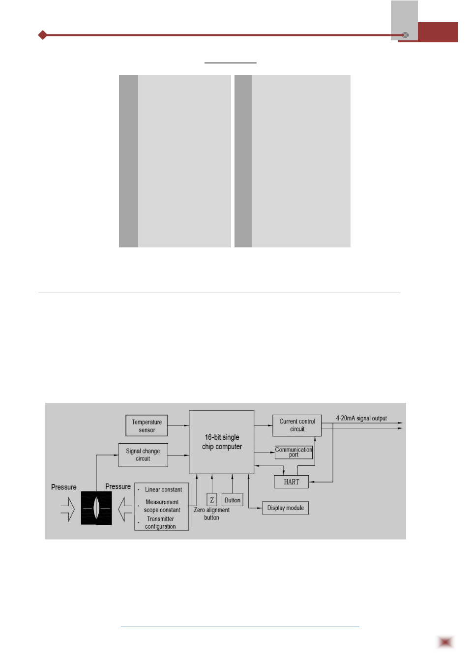
2.2 Working Principle
As indicated in the working principle diagram, the outside pressure or differential pressure
will cause some change in the sensor capacitance value. Through the digital signal conversion, it
will change into the frequency signal, which is sent to the microprocessor. After the calculation by
microprocessor, a current control signal will be output to the current control circuit, converted into
analogue 4-20mA current output. Meanwhile, the microprocessor is responsible for the
interactive and other actions (display and setting). The communication port used for digital
communication needs the special port of our company. HART module will realize the transmitter
HART communication.
1
Cover
14
Cover lock bolt
2
O-ring
15
Sensor
3
Wiring terminals cover
16
O-ring
4
Mounting bolts of circuit board
17
O-ring
5
Thunder-proof wiring circuit
board
18
Position code plate
6
Name plate
19
Zero alignment plate
7
Housing body
20
Housing body lockup bolt
8
Meter head
21
Parallel wires
9
Mounting bolts of meter head
22
Circuit board
10
Meter head cover
23
Nut M10
11
Drain/ vent valve
24
Integrated
3-valve
group
(optional)
12
Template
25
Welded connector (optional)
13
Bolts M10
26
Flange (optional)