Electrical connections – ABUS Technologies DP Series Smart Pressure Transmitter User Manual
Page 9
ABUS TECHNOLOGIES INC.
M94
9
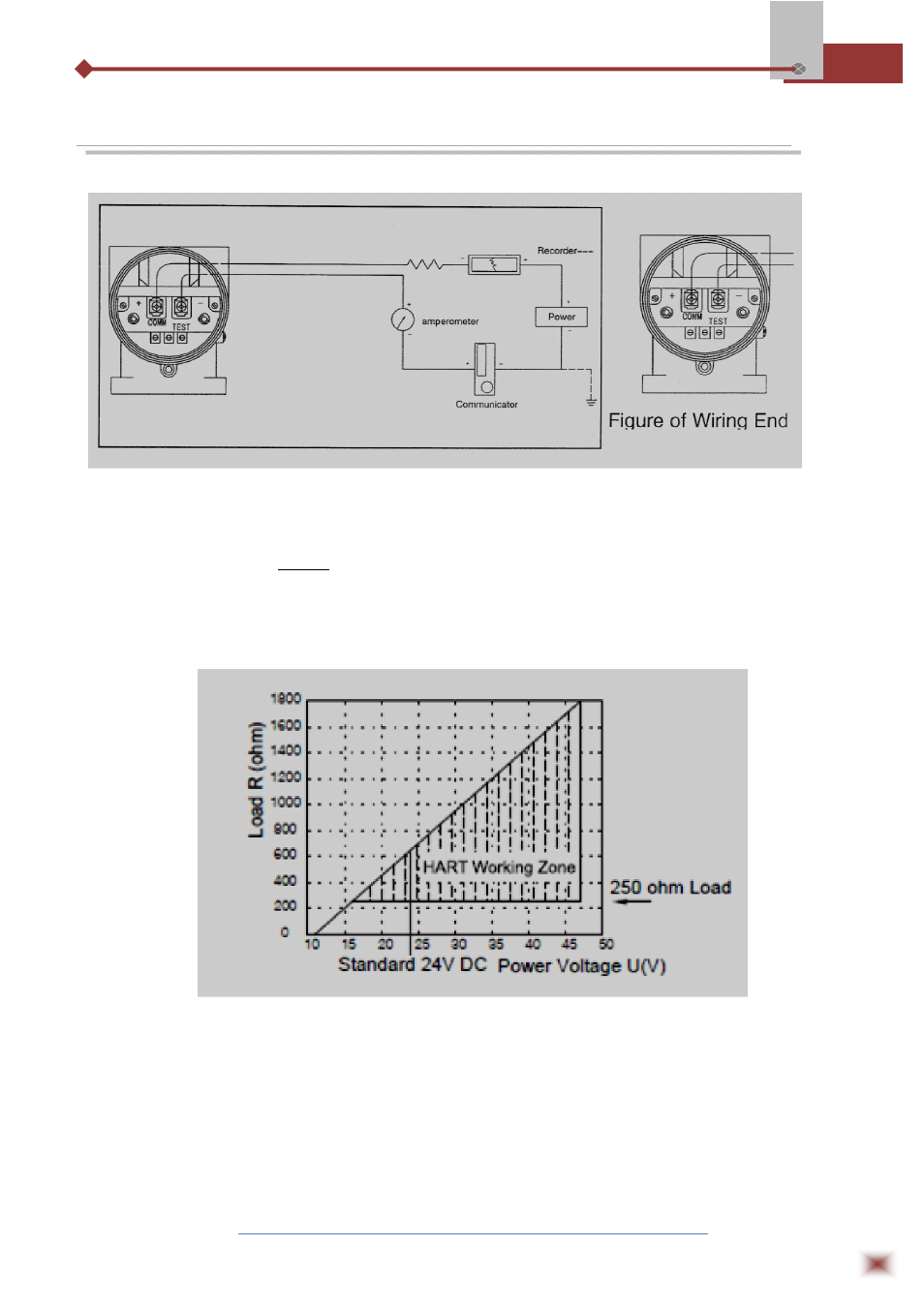
3. ELECTRICAL CONNECTIONS
Electrical Port: :NPT1/2 load resistance of cable sealed connector: (4-20mA)
=
− 14
0.02
−
where: U is power voltage, R
D
is cable internal resistance
(Note 1: User can install the distributor or safe barriers per the on-site and design
requirements. For details, see the usage of distributor and safe barrier.)
It is recommended to choose the explosion-proof impulse terminal with the cable
diameter of ö8 – 12. The connection terminal is set with test terminal, convenient for the online
test of the operator.
Signal terminal is situated in a separate housing of the electrical box. Screw up the meter
cover for wiring. The upper end is for signal, while the lower end is for test meter. Fig. 2-13
indicated the terminal location. The test terminal is used for connecting any optional indicator