Applied Motion 2035 User Manual
Page 3
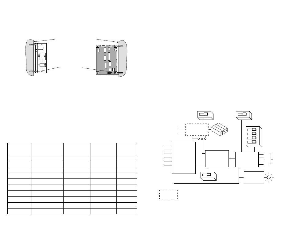
extspeed
Amplifier
Optical
Isolation
com
step
dir
enable
tach+
tach-
cw
wiper
ccw
Step
Sequencer
Oscillator
50% idle
STEP/SLEW JUMPER
current setting
full step/
half step
step
accel
decel
speed adj
A+
A-
B+
B-
to
motor
Block Diagram
2035 O only
smooth flat surface
#4 screws
wide side mount
narrow side mount
12-35VDC
+5V
Regulator
power
LED
(red)
-3-
-14-
Recommended Motors
Motor
Size
Winding
Max Torque
Current
Number
inches
Connection
oz-in
Amps
5014-842
1.38 x 1.38 x 1.57
4 lead
19
1.0
HT17-068
1.65 x 1.65 x 1.30
parallel
23
1.0
HT17-071
1.65 x 1.65 x 1.54
parallel
30
1.25
HT17-075
1.65 x 1.65 x 1.85
parallel
40
1.75
5023-127
2.22 x 2.22 x 2.25
4 leads
110
2.0
5023-149
2.22 x 2.22 x 3.25
parallel
140
2.0
HT23-393
2.22 x 2.22 x 1.54
parallel
75
1.4
HT23-396
2.22 x 2.22 x 2.13
parallel
175
1.4
HT23-399
2.22 x 2.22 x 2.99
parallel
260
1.4
5034-324
3.38 x 3.38 x 2.50
series
190
2.0
Mounting the Drive
You can mount your drive on the wide or the narrow side of the chassis. If you
mount the drive on the wide side, use #4 screws through the four corner holes. For
narrow side mounting applications, you can use #4 screws in the two side holes.
The amplifiers in the drive generate heat. Unless you are running at 1 amp or below,
you may need a heat sink. To operate the drive continuously at maximum power
you must properly mount it on a heat sinking surface with a thermal constant of no
more than 4
°
C/watt. Applied Motion Products can provide a compatible heat sink.
Often, the metal chassis or enclosure of your system will work as an effective heat
sink.
Never use your drive in a space where there is no air flow or where
other devices cause the surrounding air to be more than 70˚C. Never
put the drive where it can get wet or where metal particles can get on
it.
Features
• Drives sizes 14 through 23 step motors. Can also be used in some cases to drive
size 34 motors. See page 14 for a list of recommended motors.
• Pulse width modulation switching amplifiers
• Phase current from 0.125 to 2.0 amps (switch selected, 16 settings)
• Step and direction and enable inputs, optically isolated, 5-24V.
• Inputs can be sourcing (PNP) or sinking (NPN) type
• Full and half step (switch selected)
• Automatic 50% idle current reduction (switch selected)
• Built in ramping pulse generator with adjustable speed, accel, decel (2035 O)
• 0 - 5000 Hz oscillator speed range (2035 O)
• Optically isolated Tach output for monitoring speed (2035 O)
• Speed can be set from on-board trimpot or external pot (2035 O)
• Compact size: 1.5 x 3 x 4 inches.