Applied Motion 2035 User Manual
Page 4
-4-
-13-
Choosing a Power Supply
Voltage
Current
The maximum supply current you will need is the sum of the two phase
currents. However, you will generally need a lot less than that, depending on the
motor type, voltage speed and load conditions. That's because the 2035 and 2035
O use switching amplifiers, converting a high voltage and low current into lower
voltage and higher current. The more the power supply voltage exceeds the motor
voltage, the less current you’ll need from the power supply.
We recommend the following selection procedure:
1. If you plan to use only a few drives, get a power supply with at least twice
the rated phase current of the motor.
2. If you are designing for mass production and must minimize cost, get one
power supply with more than twice the rated current of the motor. Install the motor
in the application and monitor the current coming out of the power supply and into
the drive at various motor loads. This will tell you how much current you really
need so you can design in a lower cost power supply.
If you plan to use a regulated power supply you may encounter a problem with
current foldback. When you first power up your drive, the full current of both motor
phases will be drawn for a few milliseconds while the stator field is being
established. After that the amplifiers start chopping and much less current is drawn
from the power supply. If your power supply thinks this initial surge is a short
circuit it may “foldback” to a lower voltage. With many foldback schemes the
voltage returns to normal only after the first motor step and is fine thereafter. In that
sense, unregulated power supplies are better. They are also less expensive.
Chopper drives work by switching the voltage to the motor terminals on and off
while monitoring current to achieve a precise level of phase current. To do this
efficiently and silently, you’ll want to have a power supply with a voltage rating
atleast five times that of the motor. Depending on how fast you want to run the
motor, you may need even more voltage than that. More is better, the only upper
limit being the maximum voltage rating of the drive itself: 35 volts. If you choose
an unregulated power supply, do not exceed 24 volts. This is because unregulated
supplies are rated at full load current. At lesser loads, like when the motor’s not
moving, the actual voltage can be up to 1.4 times the rated voltage.
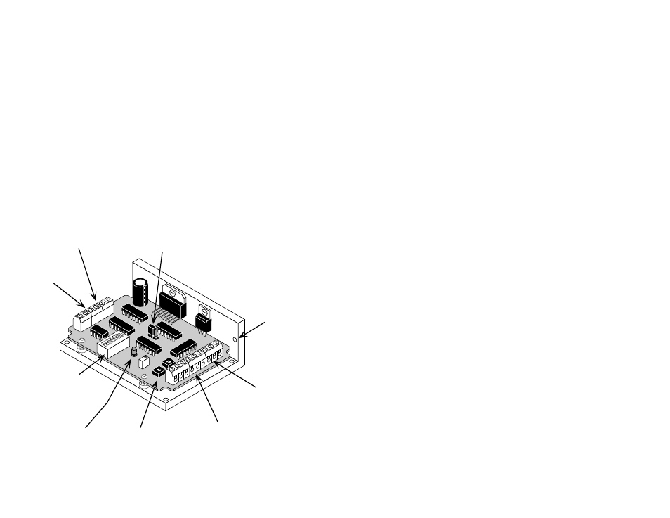
logic
connector
STEP, DIR, EN
trimpots for adjusting
LED - indicates
DC power
oscillator speed, accel and
decel rates
(2035 O only)
mounting
hole (1 of 6)
power
connector
motor
connector
jumper for selecting
oscillator mode
(2035 O only)
Getting Started
a 12-35 volt DC power supply for the motor. Please read the section entitled
Choosing a Power Supply for help in choosing the right power supply.
5 to 24 volts DC, to activate the optoisolation circuits (if you are using an
O
drive and don't have 5 - 24V available, see page 12.)
a source of step pulses capable of sinking at least 5 mA
if your application calls for bidirectional rotation, you'll also need a direction
signal, capable of sinking 5 mA
a compatible step motor (see page 14)
a small flat blade screwdriver for tightening the connectors and adjusting the
oscillator
•
•
•
•
•
•
To use your Applied Motion Products motor control, you will need the following:
The sketch below shows where to find the important connection and adjustment
points. Please examine it now.
switches for
selecting current,
idle current,
full or half stepping,
speed pot (2035 O)
connector for external
speed pot/signal
& tach output
(2035 O only)