Setting phase current, Selecting between full and half step operation, Amps/phase – Applied Motion 2035 User Manual
Page 8: Current setting table
-8-
-9-
.125
AMPS/PHASE
CURRENT
BASE =
125mA
125
250
500
1000
.25
AMPS/PHASE
.375
AMPS/PHASE
.5
AMPS/PHASE
.625
AMPS/PHASE
.75
AMPS/PHASE
.875
AMPS/PHASE
1
AMPS/PHASE
1.125
AMPS/PHASE
1.25
AMPS/PHASE
1.375
AMPS/PHASE
1.5
AMPS/PHASE
1.625
AMPS/PHASE
1.75
AMPS/PHASE
1.875
AMPS/PHASE
2
AMPS/PHASE
CURRENT
BASE =
125mA
125
250
500
1000
CURRENT
BASE =
125mA
125
250
500
1000
CURRENT
BASE =
125mA
125
250
500
1000
CURRENT
BASE =
125mA
125
250
500
1000
CURRENT
BASE =
125mA
125
250
500
1000
CURRENT
BASE =
125mA
125
250
500
1000
CURRENT
BASE =
125mA
125
250
500
1000
CURRENT
BASE =
125mA
125
250
500
1000
CURRENT
BASE =
125mA
125
250
500
1000
CURRENT
BASE =
125mA
125
250
500
1000
CURRENT
BASE =
125mA
125
250
500
1000
CURRENT
BASE =
125mA
125
250
500
1000
CURRENT
BASE =
125mA
125
250
500
1000
CURRENT
BASE =
125mA
125
250
500
1000
CURRENT
BASE =
125mA
125
250
500
1000
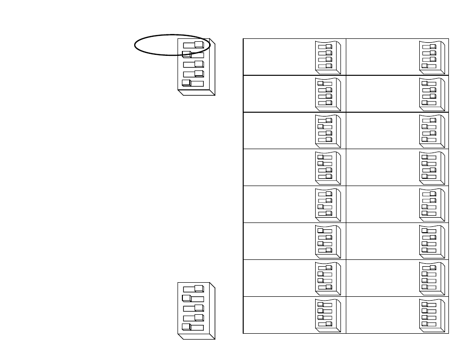
Current Setting Table
Setting Phase Current
Before you turn on the power supply the first time, you need to set the driver for the
proper motor phase current. The rated current is usually printed on the motor label.
The 2035 drive current is easy to set. If you wish, you can learn a simple formula
for setting current and never need the manual again. Or you can skip to the table on
the next page, find the current setting you want, and set the DIP switches according
to the picture.
Current Setting Formula
Locate the bank of tiny switches near the motor connector. Four of the switches
have a value of current printed next to them, such as 500 and 1000. Each switch
controls the amount of current, in milliamperes (mA), that it's label indicates. There
is always a base of current of 125 mA. To add to that, slide the appropriate switches
toward their labels. You may need your small screwdriver for this.
Example
Suppose you want to set the driver for 1.25 amps
per phase (1250 mA). You need the 125 mA base
current plus another 1000 and 125 mA.
1250 = 125 + 1000 +125
Slide the 125 and 1000 mA switches toward the labels
as shown in the figure.
Selecting Between Full and Half Step Operation
HALF STEP
125
250
500
1000
HALF STEP
125
250
500
1000
Locate the bank of switches near the motor
connector. One switch is labeled on the circuit
board as
HALF STEP.
Sliding the switch toward the
HALF STEP label
sets the driver for that mode of operation. The
opposite position is full step. When set to full
step, the driver always uses "two phases on" mode
to provide maximum motor torque.