Applied Motion 2035 User Manual
Page 5
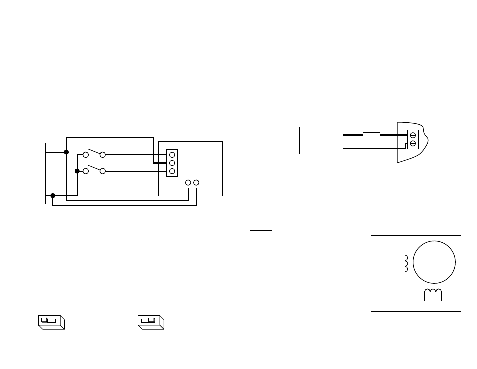
+VDC-
motor
supply
12-35 VDC
+
–
Connecting the Motor
Warning: When connecting the motor to the driver, be sure that the
motor power supply is off. Secure any unused motor leads so that they
can't short out to anything. Never disconnect the motor while the drive
is powered up. Never connect motor leads to ground or to a power
supply!
You must now decide how to connect your
motor to the drive.
Four lead motors can only be connected
one way. Please follow the sketch at the
right.
Six lead motors can be connected in
series or center tap. In series mode, motors
produce more torque at low speeds, but
cannot run as fast as in the center tap
configuration. In series operation, the motor
should be operated at 30% less than the rated current to prevent overheating.
Winding diagrams for both connection methods are shown on the next page
Connecting the Power Supply
A+
A-
B+
B-
4
lead
motor
Red
Blue
Yellow
White
4 Leads
fuse
If you need information about choosing a power supply, please read
Choosing a
Power Supply on page 13 of this manual.
If you're power supply does not have a fuse on the output or some kind of short
circuit current limiting feature you need to put a 3 amp slow blow fuse between the
drive and power supply. Install the fuse on the + power supply lead.
Connect the motor power supply + terminal to the driver terminal labeled "+VDC".
Connect power supply – to the drive terminal labeled "-". Use no smaller than 20
gauge wire. Be careful not to reverse the wires. Reverse connection will
destroy your driver, void your warranty and generally wreck your day.
-12-
-5-
Motor
Power
Supply
12-24
VDC
+
-
Run/Stop switch (closed=run)
Direction
switch
2035 O
STEP COM DIR
+VDC-
Idle Current Reduction
The 2035 and 2035 O drives include a feature that automatically reduces the motor
current by 50% when the motor is not moving. This is known as idle current
reduction.
For qualifying OEMs, we can change the amount of current reduction during the
manufacturng process.
If you want full current all the time, move the switch away from the
50% IDLE label.
Using Mechanical Switches with 2035 O Drive
The 2035 O was designed to be used with active logic and for that reason has
optically isolated inputs. To activate the optoisolators a small, but not insignificant
amount of current at 5 to 24 volts DC is required.
In some applications, step motors and drives are used with mechanical switches
only and there is no readily available source of 5 - 24 volts.
In these instances, the motor power supply can be used if it does not exceed 24
VDC. The recommended wiring diagram is shown below.
Check your wiring carefully before turning on the power supply!
2
50% IDLE
50% Idle Current
50% IDLE
No Idle Current Reduction
2