Limit switches, Jogging – Applied Motion 1240i-485 User Manual
Page 11
-10-
-11-
Limit Switches
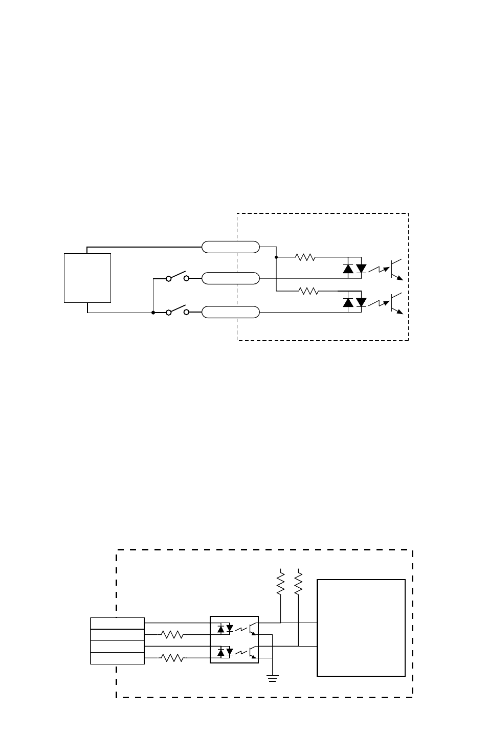
The 1240i has two limit switch inputs, LIMIT CW and LIMIT CCW. By connecting
switches or sensors that are triggered by the motion of the motor or load, you can
force the 1240i to operate within certain limits. This is useful if a program error
could cause damage to your system by traveling too far.
The limit inputs are optically isolated. This allows you to choose a voltage for your
limit circuits of 5 to 24 volts DC. This also allows you to have long wires on limit
sensors that may be far from the 1240i with less risk of intoducing noise to the
1240i. The schematic diagram of the limit switch input circuit is shown below.
Jogging
Two of the 1240i input terminals are provided for jogging the motor. The inputs are
labeled “JOG CW” and “JOG CCW”. Activating one of the inputs commands the
drive to move the motor at a pre-designated speed until the contact is opened. A
relay or mechanical switch can be used to activate the jog inputs. 5-24 volt circuitry
can be used. The schematic diagram of the input circuit is shown below.
If you’re using a switch or relay, wire one end to the JOG input and the other to the
power supply negative (-) terminal. Then connect the COM input to the power sup-
ply positive (+) terminal.
2200
2200
inside 1240i
COM
JOG CW
JOG CCW
+
5-24
VDC
SUPPLY
-
1240i
Controller
Chip
2200
10K
+5V +5V
3
4
1
2
CW LIMIT+
CW LIMIT–
CCW LIMIT+
CCW LIMIT–
inside 1240i