1240i, Wiring outputs – Applied Motion 1240i-485 User Manual
Page 15
-14-
-15-
Wiring Outputs
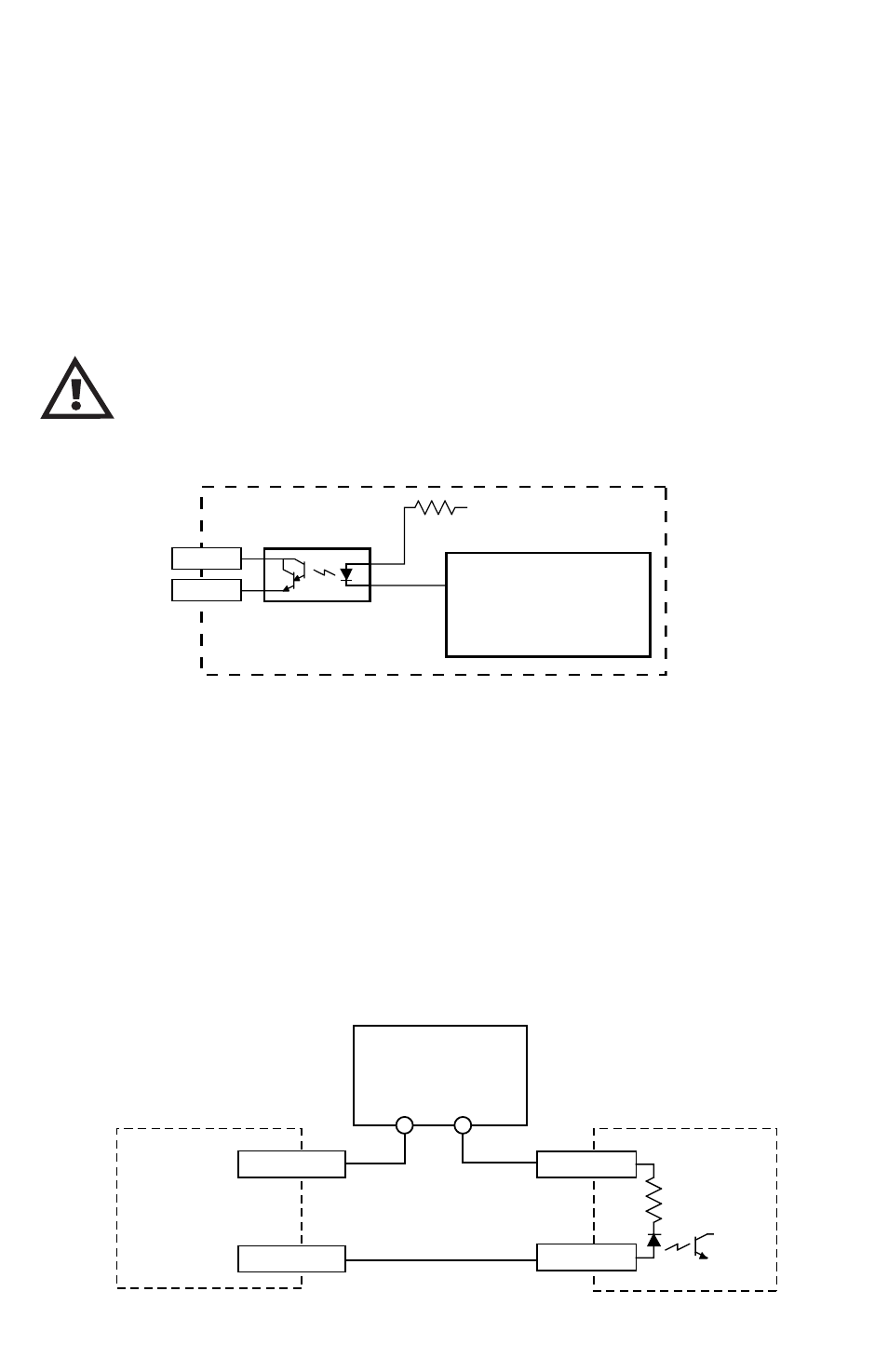
Before we discuss the output conditions, we need to talk about the circuitry. All three
1240i outputs are optically isolated. That means that there is no electrical connec-
tion between the indexer-drive and the output terminals. The signal is transmitted
to the output as light. What you “see” is a transistor (NPN type) that closes, or
conducts current, when the output is “low”. When the output is high, the transistor
is open.
The maximum voltage between any pair of + and - output ter-
minals is 24 volts DC. Never connect AC voltages to the 1240i
output terminals. Maximum current is 100 mA per output.
330
+5V
OUT1–
OUT1+
1240i
Controller Chip
inside 1240i
PLC
COMMON
INPUT
1240i
OUTPUT-
OUTPUT+
5-24 VDC
Power Supply
+
–
Since there is no electrical connection to the 1240i, you must provide the source of
current and voltage, typically from a power supply. You must also limit the current to
less than 100 mA so that the output transistor is not damaged. You would normally
use a resistor for this, but some loads (such as PLC inputs) limit the current auto-
matically.
The diagram below shows how to connect an 1240i output to an optically isolated
PLC input.
Schematic Diagram of 1240i Output Circuit