Wiring inputs – Applied Motion 1240i-485 User Manual
Page 13
-12-
-13-
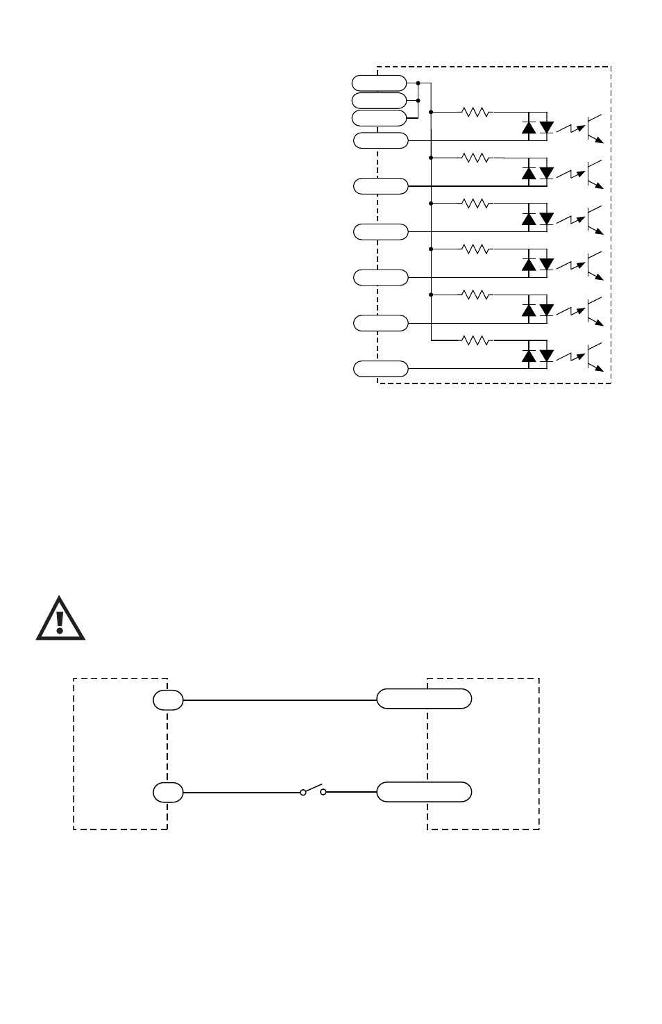
Wiring Inputs
The 1240i input circuits can be used with
sourcing or sinking signals, 5 to 24 volts.
This allows connection to TTL circuits,
PLCs, relays and mechanical switches.
Because the input circuits are isolated, they
require a source of power. If you are con-
necting to a TTL circuit or to a PLC, you
should be able to get power from the PLC or
TTL power supply. If you are using relays or
mechanical switches, you will need a 5-24
V power supply. This also applies if you are
connecting the 1240i inputs to another Si
product from Applied Motion, like the Si-1
and Si-100 indexers or the 3540i, Si3540,
Si5580, 7080i and BL series drives.
Connecting an Input to a Switch or Relay
Use normally open momentary switch to trigger 1240i using Wait Input instruction.
Use single throw switch if using the If Input instruction for program branching.
Use normally open momentary switch for jogging.
Note: If current is flowing into or out of a 1240i input, the logic state of that input is
low. If no current is flowing, or the input is not connected, the logic state is high.
The diagrams on the following pages show how to connect 1240i inputs to various
devices.
The maximum voltage that can be applied to an input terminal
is 24 volts DC. Never apply AC voltage to an input terminal.
2200
2200
2200
2200
2200
2200
inside Si3540
COM
COM
COM
IN1
IN2
IN3
IN4
CWJOG
CCWJOG
1240i
switch or relay
(closed=logic low)
IN
COM
5-24
VDC
Power
Supply
-
+