Applied Motion 3540MO User Manual
Page 4
The amplifiers in the drive generate heat. Unless you are running at 1 amp or
below, you may need a heat sink. To operate the drive continuously at maximum
power you must properly mount it on a heat sinking surface with a thermal constant
of no more than 4˚C/watt. Applied Motion Products can provide a compatible heat
sink. Often, the metal enclosure of your system will make an effective heat sink.
Never use your drive where there is no air flow or where other devices
cause the surrounding air to be more than 70˚C. Don't put the drive
where it can get wet or where metal particles can get on it.
smooth flat surface
#4 screws
wide side mount
narrow side mount
-4-
-17-
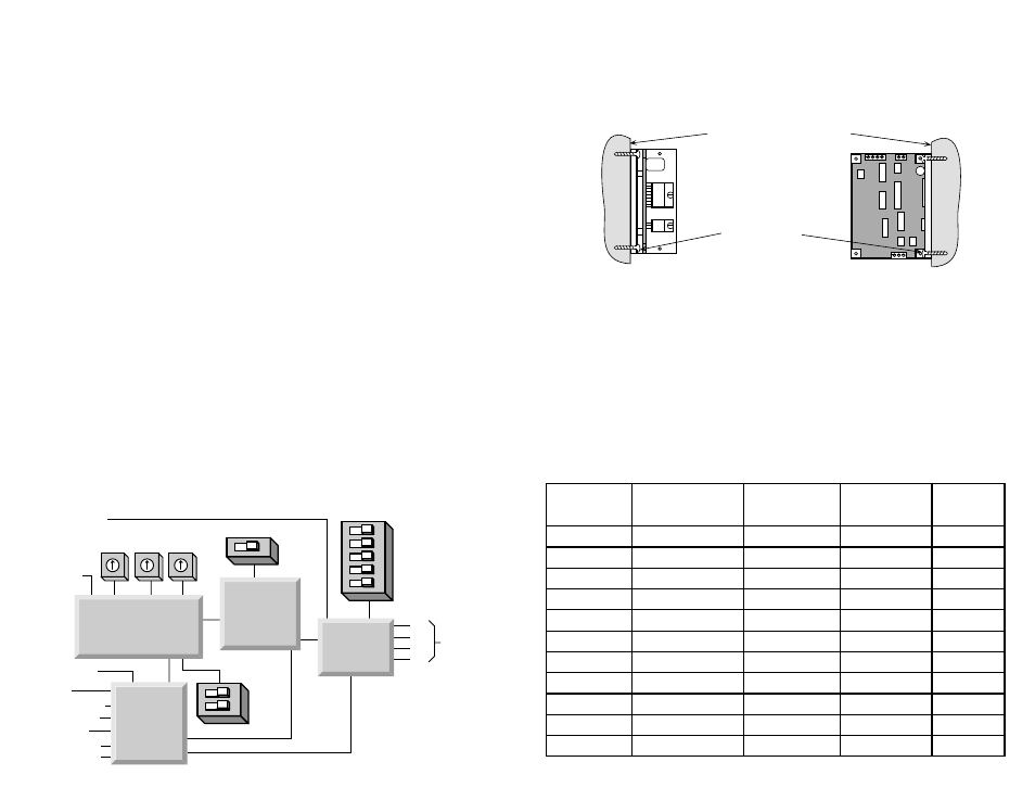
Mounting the Drive
You can mount your drive on the wide or the narrow side of the chassis. If you
mount the drive on the wide side, use #4 screws through the four corner holes. For
narrow side mounting applications, you can use #4 screws in the two side holes.
run
direction
common
ext
speed
input
12-42 VDC
hi/lo speed
current
0.4 to 3.5
A/phase
ext speed
joystick
A+
A–
B+
B–
to
motor
enable
tach out+
tach out-
50% idle
accel
LO
speed
HI
speed
Microstep
Sequencer
MOSFET
Amplifier
Optical
Isolation
Digital Oscillator
&
Joystick Interface
Introduction
Thank you for selecting an Applied Motion Products motor control. We hope our
dedication to performance, quality and economy will make your motion control
project successful.
If there's anything we can do to improve our products or help you use them better,
please call or fax. We'd like to hear from you. Our phone number is (800) 525-
1609 or you can reach us by fax at (831) 761–6544.
Features
• Digital oscillator provides smooth accel/decel ramps and precise speed control.
• Powerful microstepping amplifier provides high torque and smooth, quiet motion.
• Accepts a wide range of motors: NEMA sizes 14 - 34, 0.4 to 3.5 amps/phase.
• Accepts a wide range of DC power supply voltages: 12 - 42 volts DC.
• Easy to configure with on-board switches and potentiometers for all settings.
• Automatic idle current reduction reduces motor and drive heating, saves power.
• Screw terminal connectors make wiring easy.
• Can operate from internal pots, external pots, 0 - 5 V analog signal, or analog joystick.
• Two speed ranges, can be selected "on the fly" by a digital signal with automatic ramping
between speeds.
• Also accepts simple, analog joystick.
• Compact size: 1.5 x 3 x 4 inches.
• Digital inputs are optically isolated, 5 - 24 volts, sourcing or sinking.
• Tach Out signal allows easy measurement of speed, optically isolated, 5 - 24 volts.
• Enable input allows motor current to be shut off on command.
Block Diagram
Recommended Motors
Motor
Size
Winding
Max Torque
Current
Number
inches
Connection
oz-in
Amps
5014-842
1.38 x 1.38 x 1.57
4 lead
19
1.0
HT17-068
1.65 x 1.65 x 1.30
parallel
23
1.0
HT17-071
1.65 x 1.65 x 1.54
parallel
30
1.25
HT17-075
1.65 x 1.65 x 1.85
parallel
40
1.7
5023-122
2.22 x 2.22 x 2.0
parallel
60
2.0
5023-123
2.22 x 2.22 x 3.0
parallel
100
2.5
5023-124
2.22 x 2.22 x 4.0
parallel
150
3.5
HT23-394
2.22 x 2.22 x 1.54
parallel
60
2.8
HT23-397
2.22 x 2.22 x 2.13
parallel
140
2.8
HT23-400
2.22 x 2.22 x 2.99
parallel
180
2.0
5034-348
3.38 x 3.38 x 2.50
parallel
130
3.5