3540 mo – Applied Motion 3540MO User Manual
Page 9
-9-
-12-
In both operating modes, the accel/decel rate is set by the ACCEL pot. The
range is 1 to 250 rev/sec/sec. Turning the pot clockwise makes the motor start and
stop faster, but if you set it too high the motor may run out of torque and stall.
In nearly all cases, the accel/decel rate you set is respected by the 3540 MO. For
example, if you switch the SPD input while the motor is moving, the drive will
change speeds smoothly. If you are operating in EXT SPEED mode and make a
sudden change in the voltage to the WPR terminal, the drive accelerates (or
decelerates) to the new speed smoothly, according to the accel pot setting.
The only time the drive makes an instant change is when the SPD input is on and
the RUN input goes off. That is done so that you can stop instantly (and exactly)
from a low speed.
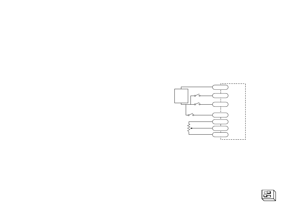
Typical wiring for Oscillator Mode using external speed control pot
5k
Ω
pot
speed switch (closed=lo speed)
cw
ccw
3540 MO
COM
DIR
RUN
SPD
CCW
WPR
CW
+
5-24
VDC
SUPPLY
-
direction switch
run/stop switch
(closed=run)
open collector TTL devices are directly compatible with this drive, as are typical
PLC and proximity sensor outputs.
Sinking Circuits (NPN)
If your output devices prefer to sink current, then connect the COM terminal to your
positive power supply. If you are using a TTL circuit to drive the 3540 MO, connect
the COM terminal to your 5 volt bus. No ground connection is needed. If you are
using a PLC or proximity sensor, you'll need a power supply.
Sourcing circuits (PNP)
If your output devices can only source current (some PLC outputs are this way),
connect the COM terminal to the ground of the DC power supply that powers your
output circuits.
Note: We refer to an input as being ON when current is flowing
through the input. A signal is OFF when no current is flowing. An
input is OFF when COM and the input terminal are at the same voltage,
or when the input is left unconnected (open).
The ENABLE input allows the user to turn off the current to the motor by setting this
signal on. The logic circuitry continues to operate, so the drive "remembers" the
step position even when the amplifiers are disabled. However, the motor may move
slightly when the current is removed depending on the exact motor and load
characteristics. If you have no need to disable the amplifiers, you don't
need to connect anything to the
ENABLE input.
Connecting the Motor
Warning: When connecting the motor to the driver, be sure that the
motor power supply is off. Secure any unused motor leads so that
they can't short out to anything. Never disconnect the motor while the
drive is powered up. Never connect motor leads to ground or to a
power supply!
You must now decide how to connect your motor to the drive. Page 13 shows
several ways to connect your motor to the 3540 MO.
Speed Control from a 0 to 5 Volt Analog Signal
In oscillator mode, the 3540MO can rotate the motor a speed proportional to an
analog voltage. The voltage must be applied to the WPR terminal. The direction of
rotation will be controlled by the digital DIR input and the motor can be stopped
either by setting the analog input voltage to 0 or by turning the digital RUN signal
off.
To use the 3540 MO in this mode, set switch #1 away from the
JOYSTICK label, and set switch #2 toward the EXT SPEED label.
ext speed
joystick
12