Applied Motion 3540MO User Manual
Page 5
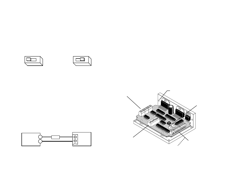
power connector
• DC power supply
• motor
trim pots
• accel/decel rate
• low speed
• high speed
input connector
• run/stop (cw limit)
• dir (ccw limit)
• high/low speed select
• amp enable
• ext speed pot/joystick
• tach out
mounting hole (1 of 6)
DIP switches
• motor current
• idle current reduction
• joystick mode
• ext speed mode
-16-
-5-
Getting Started
To use your Applied Motion Products motor control, you will need the following:
• a 12-42 volt DC power supply for the motor. Please read the section entitled
Choosing a Power Supply for help in choosing the right power supply.
• a compatible step motor
• a small flat blade screwdriver for tightening the connectors
• For Joystick mode, you'll need an 3 terminal analog joystick with 1K - 5K
impedance. If you want to use limit switches, you'll need
normally open switches
and a 5 - 24 volt power supply.
• For Oscillator mode, you'll need run/stop and direction signals (or switches).
Because the input circuits are optically isolated, you may also need a 5 - 24 volt
DC power supply. (See pages 8-10 for details.) If you want to control the motor
speed externally, you need a 1K - 5K pot or a 0 - 5 volt analog signal.
The sketch below shows where to find the important connection and adjustment
points. Please examine it now.
Connecting the Power Supply
If you need information about choosing a power supply, please read
Choosing a
Power Supply located on page 18 of this manual. The PS430 from Applied Motion
Products is a good supply for this drive.
If your power supply does not have a fuse on the output or some kind of short
circuit current limiting feature you need to put a 4 amp fast acting fuse between the
drive and power supply. Install the fuse on the + power supply lead.
Connect the motor power supply as shown below. Use no smaller than 20 gauge
wire. Be careful not to reverse the wires. Reverse connection will destroy
your driver, void your warranty and generally wreck your day.
50% IDLE
3
3
50% IDLE
Idle Current Reduction Selected
No Current Reduction
Idle Current Reduction
Your drive is equipped with a feature that automatically reduces the motor current
by 50% anytime the motor is not moving. This reduces drive heating by about 50%
and lowers motor heating by 75%. This feature can be disabled if desired so that
full current is maintained at all times. This is useful when a high holding torque is
required. To minimize motor and drive heating we highly recommend that you
enable the idle current reduction feature unless your application strictly forbids it.
Idle current reduction is enabled by sliding switch #3 toward the
50% IDLE label,as
shown in the sketch below. Sliding the switch away from the
50% IDLE label
disables the reduction feature.
+ VDC –
DC Power
Supply
12-42 volts
3540MO
+
4A fuse
–
Always use the blue & white Applied
Motion screwdriver with this
connector. Larger screwdrivers may
remove the plastic dimples that
prevent the screws from falling out.