Applied Motion 3540MO User Manual
Page 8
-8-
-13-
Oscillator mode is selected by moving switch #1 away from the word Joystick.
There are two speed ranges in oscillator mode. One is the low speed range, which
is activated when the SPD input is on. The low speed can be set from 0 to 5 rev/sec
(0 - 300 rpm) by adjusting the LO SPEED pot. Turning the pot clockwise increases
the speed.
The high speed setting is used when the SPD input is off, or open. If switch #2 is
toward the words EXT SPEED, then the high speed is proportional to the voltage
applied to the WPR terminal, and is trimmed by the HI SPEED pot. You can connect
an external 1K - 5K pot to the WPR, CW and CCW terminals, or you can apply a 0 to
5 volt analog signal to the WPR terminal (ground your analog signal to the CCW
pin.) The high speed range is 0 - 25 rev/sec (0 - 1500 rpm.) You can reduce the
range by turning down the HI SPEED pot. For example, if you want the motor to go
750 rpm when the external pot is on maximum, turn the HI SPEED pot down about
half way.
When switch #2 is away from the EXT SPEED label, the high speed is set by the HI
SPEED pot and the WPR input does nothing.
Never apply more than 5 volts DC or less than 0 volts to the WPR pin.
A+
A-
B+
B-
8
lead
motor
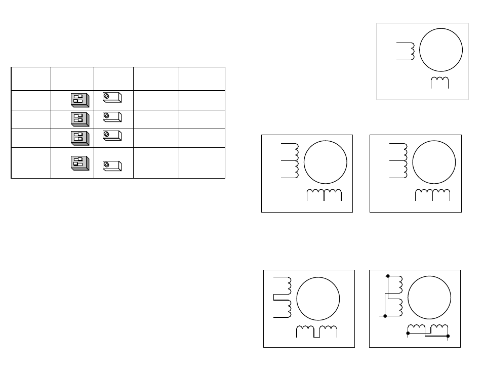
8 Leads Series Connected
A+
A-
NC
B+
B-
NC
6
lead
motor
Red
Black
Red/
Wht
Green
Grn/Wht
White
A+
A-
NC
B+
B-
NC
6
lead
motor
Grn/Wht
White
Green
Red
Red/
Wht
Black
6 Leads Series Connected
6 Leads Center Tap Connected
8 Leads Parallel Connected
A+
A-
B+
B-
8
lead
motor
Orange
Org/Wht
Blk/Wht
Black
Red
Red/
Wht
Yel/
Wht
Yellow
Orange
Org/
Wht
Blk/Wht
Black
Red
Red/Wht
Yel/
Wht
Yel
low
Eight lead motors can also be connected in two ways: series or parallel. As with
six lead motors, series operation gives you more torque at low speeds and less
torque at high speeds. In series operation, the motor should be operated at 30%
less than the rated current to prevent over heating. The wiring diagrams for eight
lead motors are shown below.
A+
A-
B+
B-
4
lead
motor
Red
Blue
Yellow
White
4 Leads
Four lead motors can only be connected
one way. Please follow the sketch at the
right.
Six lead motors can be connected in
series or center tap. In series mode, motors
produce more torque at low speeds, but
cannot run as fast as in the center tap
configuration. In series operation, the motor
should be operated at 30% less than rated
current to prevent overheating. Wiring diagrams for both connection methods are
shown below. NC means not connected to anything.
Oscillator Mode
In oscillator mode, the 3540MO uses the direction set by the DIR input. Off, or
open, gives clockwise motion, if the motor is wired according to pages 12 and 13.
Motor speed and the function of the RUN input can be determined from the
following table.
SPD
switch
speed set
when RUN
when RUN
input
#2
by
goes ON
goes OFF
ON
accel to speed
instant stop
ON
accel to speed
instant stop
OFF/open
accel to speed
decel to stop
OFF/open
accel to speed
decel to stop
ext speed
joystick
ext speed
joystick
ext speed
joystick
ext speed
joystick
LO SPEED
LO SPEED
HI SPEED
HI SPEED
WPR input
trimmed by