Pdo 5580, Microstepping, Speed control from a 0 to 5 volt analog signal – Applied Motion PDO5580 User Manual
Page 10
-10-
Sourcing Logic
If your controller has STEP, DIR and GND (ground or common) outputs, connect
STEP- and DIR- to GND. Connect STEP+ to STEP. Connect DIR+ to DIR.
Microstepping
Most step motor drives offer a choice between full step and half step resolutions. In
full step mode, both motor phases are used all the time. Half stepping divides each
step into two smaller steps by alternating between both phases on and one phase on.
Microstepping drives like the PDO 5580 precisely control the amount of current in
each phase at each step position as a means of electronically subdividing the steps
even further. The PDO 5580 offers a choice of full and half step as well as 14 other
step resolutions. The highest setting divides each full step into 254
microsteps, providing 50,800 steps per revolution when using a 1.8° motor.
In addition to providing precise positioning and smooth motion, microstep drives
can be used for motion conversion between different units. The 25,400 step/rev
setting is provided as a means of converting motion from metric to english. (There
are 25.4 mm in an inch.) Other settings provide step angles that are decimal
degrees (36,000 steps/rev makes the motor take 0.01° steps.) Some settings are
used with lead screws. When the drive is set to 2000 steps/rev and used with a 5
pitch lead screw, you get .0001 inches/step.
PDO 5580
Drive
DIR
DIR+
DIR-
STEP
STEP+
STEP-
ENABLE
ENABLE+
GROUND
ENABLE-
Indexer
or
Controller
with
Sourcing
Outputs
= optional signal
-15-
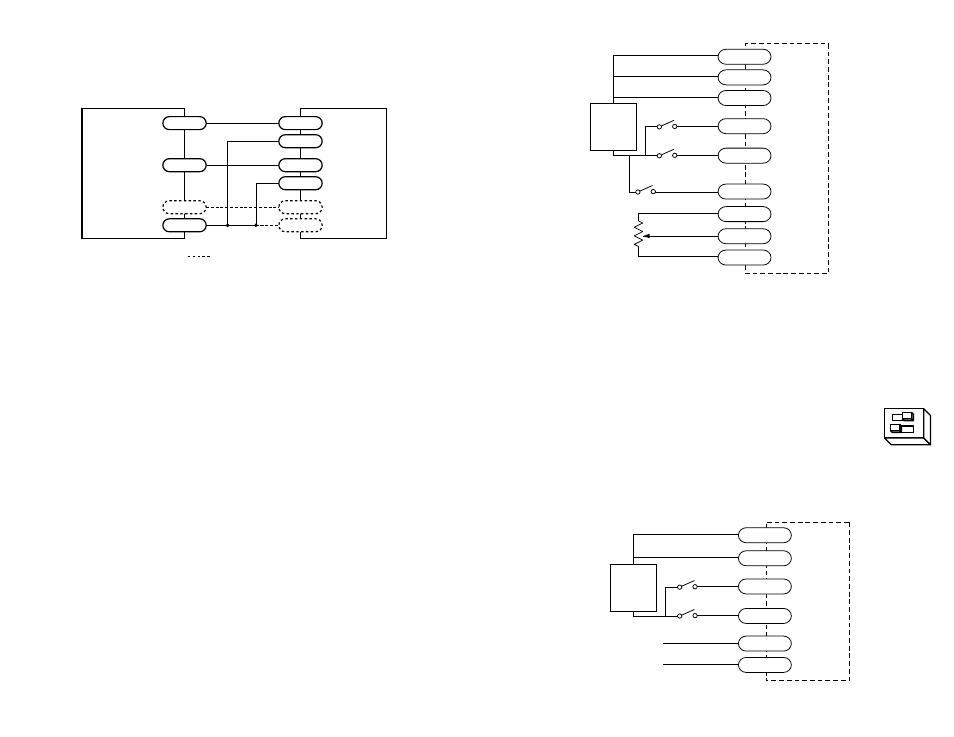
Typical Wiring for Oscillator Mode Using External Speed Control Pot
Speed Control from a 0 to 5 Volt Analog Signal
In oscillator mode, the PDO 5580 can rotate the motor at a speed proportional to an
analog voltage. The voltage must be applied to the WPR terminal. The direction of
rotation is controlled by the digital DIR input and the motor can be stopped either by
setting the analog input voltage to 0 or by turning the digital STEP signal off.
To use the PDO 5580 in this mode, set switch #1 away from the
JOYSTICK label, and set switch #2 toward the EXT SPEED label.
The HI SPEED pot sets the maximum speed (the motor speed when the analog signal
is at 5 volt DC). The range is 0 - 25 rev/sec. Wiring diagrams and a plot of speed vs
voltage are shown below and on the next page.
ext speed
joystick
Wiring for Speed Control by 0 - 5 Volt Analog Signal (with Dir Control)
5k
Ω
pot
speed switch (closed=lo speed)
cw
ccw
PDO 5580
SPEED+
DIR-
STEP-
SPEED-
CCW
WPR
CW
DIR+
STEP+
+
5-12
VDC
SUPPLY
-
direction switch
run/stop switch
(closed=run)
0 - 5V speed signal
signal return
PDO 5580
DIR+
DIR-
STEP-
CCW
WPR
STEP+
+
5-12
VDC
SUPPLY
-
direction switch
run/stop switch
(closed=run)