Applied Motion PDO5580 User Manual
Page 7
-7-
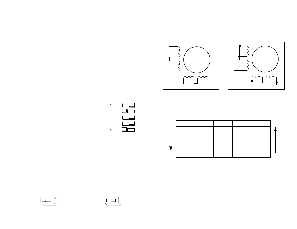
Eight lead motors can also be connected in two ways: series and parallel. As
with six lead motors, series operation gives you more torque at low speeds and less
torque at high speeds. In series operation, the motor should be operated at 30%
less than the rated current to prevent overheating. The wiring diagrams for eight lead
motors are shown below.
A+
A–
B+
B–
8
lead
motor
8 Leads Series Connected
8 Leads Parallel Connected
A+
A–
B+
B–
8
lead
motor
Orange
Org/Wht
Blk/Wht
Black
Red
Red/
Wht
Yel/
Wht
Yellow
Orange
Org/
Wht
Blk/Wht
Black
Red
Red/Wht
Yel/
Wht
Yel
low
Step
A+
A-
B+
B-
0
+
–
+
–
1
+
–
–
+
2
–
+
–
+
3
–
+
+
–
4
+
–
+
–
DIR=1
cw
DIR=0
ccw
Step 0 is the Power Up State
Step Table
(full stepping)
-18-
Idle Current Reduction
Your drive is equipped with a feature that automatically reduces the motor current by
50% anytime the motor is not moving. This reduces drive heating by about 50%
and lowers motor heating by 75%. This feature can be disabled if desired so that full
current is maintained at all times. This is useful when a high holding torque is
required. To minimize motor and drive heating we highly recommend that you use
the idle current reduction feature unless your application strictly forbids it. Idle
current reduction is enabled by sliding switch #3 toward the 50% IDLE label, as
shown in the sketch below. Sliding the switch away from the 50% IDLE label
disables the reduction feature.
Setting Phase Current
Before you turn on the power supply the first time, you need to set the driver for the
proper motor phase current. The rated current is usually printed on the motor label.
The current you set on the PDO 5580 is the peak current, not RMS.
The PDO 5580 drive current is easy to set. If you wish, you can learn a simple
formula for setting current and never need the manual again. Or you can skip to the
table on the next page, find the current setting you want, and set the DIP switches
according to the picture.
Current Setting Formula
Locate the bank of eight switches. Five of the switches have a value of current
printed next to them, such as 0.2 and 1.6. Each switch controls the amount of
current, in amperes (A), that it’s label indicates. There is always a base current of 0.5
A. To add to that, slide the appropriate switches toward their labels. You may need
your small screwdriver for this.
Example
Suppose you want to set the driver for 2.9 amps
per phase. You need the 0.5 A base
current plus another 2.0 and 0.4 A.
2.9 (TOTAL) = 0.5 (BASE) + 2.0 + 0.4
Slide the 2.0 and 0.4 A switches toward the labels
as shown in the figure.
0.2
0.4
0.8
1.6
2.0
CURRENT
(BASE=0.5A)
45678
Idle Current Reduction
Idle Current Reduction
Enabled
Disabled
50% IDLE
50% IDLE
3
3