Applied Motion PDO5580 User Manual
Page 17
-8-
SELF TEST
6
OSC BYPASS
5
Pulse & Direction Mode
SELF TEST
6
Self Test Mode
Modes of Operation
The PDO 5580 has four modes of operation, selected by three dip switches.
Self Test Mode is used for trouble shooting. If you are unsure about the motor or
signal connections to the drive, or if the PDO 5580 isn’t responding to your step
pulses, you can turn on the self test.
To activate the self test, slide switch #6 toward the
TEST label. The drive will slowly rotate the motor,
1/2 revolution forward, then 1/2 rev backward. The
pattern repeats until you slide the switch away from
the TEST label. The PDO 5580 always uses half
step mode during the self test, no matter how you set
the steps/rev switches. The self test ignores the
STEP and DIRECTION inputs while operating. The
ENABLE input continues to function normally.
Pulse & Direction Mode - the PDO 5580 receives
step pulses from an indexer such as the Applied
Motion Si-1 or Si-100. Steps/revolution are set by
switches 1 - 4 (see pages 10 - 11).
Joystick mode - speed and direction are deter-
mined by an external analog voltage. STEP and DIR
inputs can be used for limit switches. SPEED input
selects speed range. LO SPEED and HI SPEED pots
adjust the 2 speed ranges.
Oscillator mode - speed can be controlled by on-
board potentiometers and/or by an external analog
voltage. STEP input starts and stops the motor. DIR
input controls direction of rotation. SPEED input
selects the speed range.
SELF TEST
6
OSC BYPASS
5
Oscillator Mode
JOYSTICK
1
SELF TEST
6
OSC BYPASS
5
Joystick Mode
JOYSTICK
1
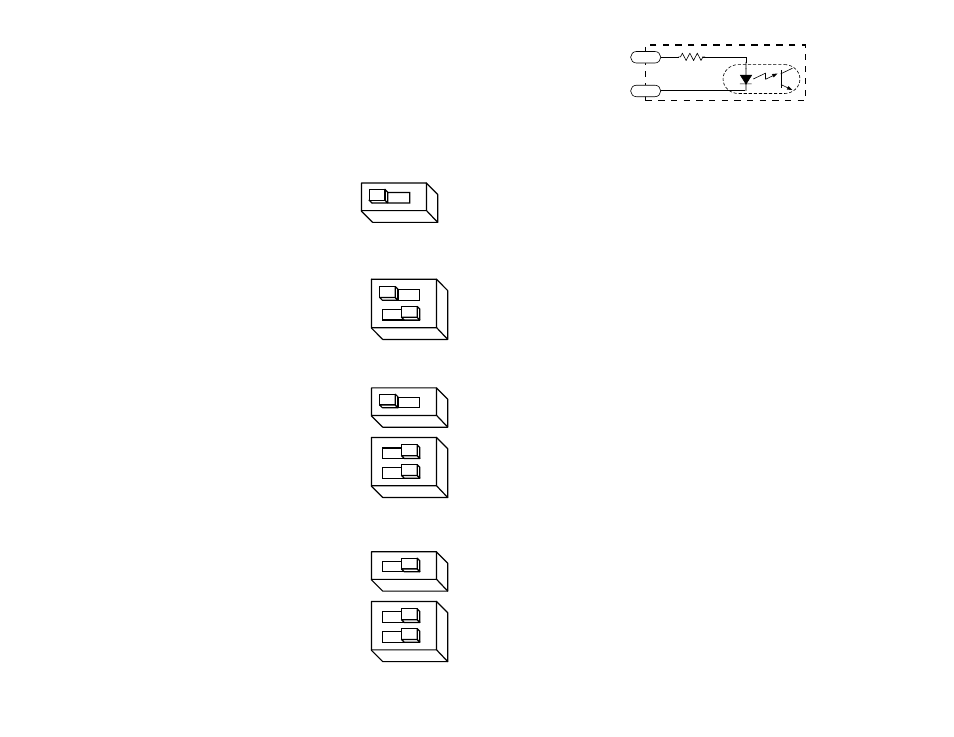
-17-
PDO 5580 Input Circuit
Sinking Circuits (NPN)
If your output devices prefer to sink current, then connect the “+” terminals to your
positive power supply, and the “-” teminals to your signals (i.e. STEP-, DIR-, etc.). If
you are using a TTL circuit to drive the PDO 5580, connect the “+” terminals to your
5 volt bus. No ground connection is needed. If you are using a PLC or proximity
sensor, you’ll need a power supply.
Sourcing circuits (PNP)
If your output devices can only source current (some PLC outputs are this way),
connect the “-” terminals to the ground of the DC power supply that powers your
output circuits. Then connect your signals to the “+” teminals (STEP+, DIR+, etc.)
Note: We refer to an input as being ON when current is flowing through
the input. A signal is OFF when no current is flowing. An input is OFF
when COM and the input terminal are at the same voltage, or when the
input is left unconnected (open).
Tach Output
The Tach Out signal is provided for measuring the motor speed. It generates 100
pulses per revolution, so if you connect a frequency counter, the speed reads out in
revs/second with two decimal places.
Do not connect the Tach output to more than 24VDC.
The current into the Tach+ terminal must not exceed 20 mA.
Enable Input
Enable Input
Enable Input
Enable Input
Enable Input
ENABLE allows the user to turn off the current to the motor by setting this signal to
logic 0. The logic circuitry continues to operate, so the drive “remembers” the step
position even when the amplifiers are disabled. However, the motor may move
slightly when the current is removed depending on the exact motor and load
characteristics.
If you have no need to disable the amplifiers, you don’t
need to connect anything to the ENABLE input.
STEP-
STEP+
R