Connecting the motor – Applied Motion Si2035 User Manual
Page 8
8
8
8
8
8
Si2035 Hardware Manual
Si2035 Hardware Manual
Si2035 Hardware Manual
Si2035 Hardware Manual
Si2035 Hardware Manual
Connecting the Motor
Connecting the Motor
Connecting the Motor
Connecting the Motor
Connecting the Motor
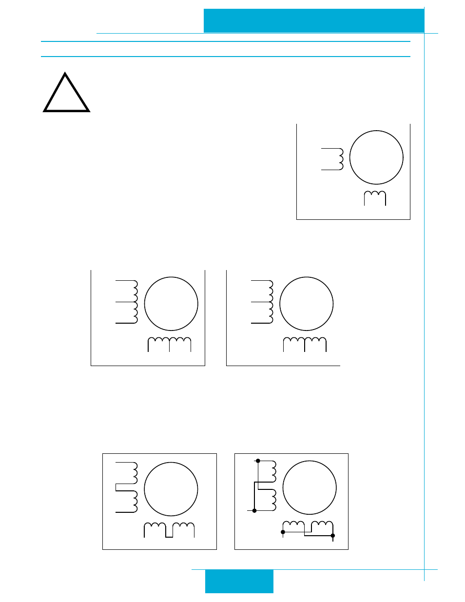
Never connect the motor to the driver when the AC power is on.
Secure any unused motor leads.
Never disconnect the motor while the AC power is on.
Never connect motor leads to ground or to a power supply.
You must now decide how to connect your motor to the drive.
Four lead motors can only be connected one way. Please
follow the sketch at the right.
Six lead motors can be connected in series or center tap. In
series mode, motors produce more torque at low speeds, but
cannot run as fast as in the center tap configuration. In
series operation, the motor should be operated at 30% less
than the rated current to prevent overheating. Winding dia-
grams for both connection methods are shown below. NC
means not connected.
Eight lead motors can also be connected in two ways: series and parallel. As with six
lead motors, series operation gives you more torque at low speeds and less torque at high
speeds. In series operation, the motor should be operated at 30% less than the rated
current to prevent over heating. The wiring diagrams for eight lead motors are shown
below.
!
A+
A–
B+
B–
4
lead
motor
Red
Blue
Yellow
White
4 Leads
A+
A–
NC
B+
B–
NC
6
lead
motor
Red
Black
Red/
Wht
Green
Grn/Wht
White
A+
A–
NC
B+
B–
NC
6
lead
motor
Grn/Wht
White
Green
Red
Red/
Wht
Black
6 Leads Series Connected
6 Leads Center Tap Connected
A+
A–
B+
B–
8
lead
motor
8 Leads Series Connected
8 Leads Parallel Connected
A+
A–
B+
B–
8
lead
motor
Orange
Org/Wht
Blk/Wht
Black
Red
Red/
Wht
Yel/
Wht
Yellow
Orange
Org/
Wht
Blk/Wht
Black
Red
Red/Wht
Yel/
Wht
Yel
low