Connection diagrams, Inside drive – Applied Motion BD10-H4-AH User Manual
Page 20
Advertising
20
BD5/10 Drive Hardware Manual
920-0065D
2/14/2014
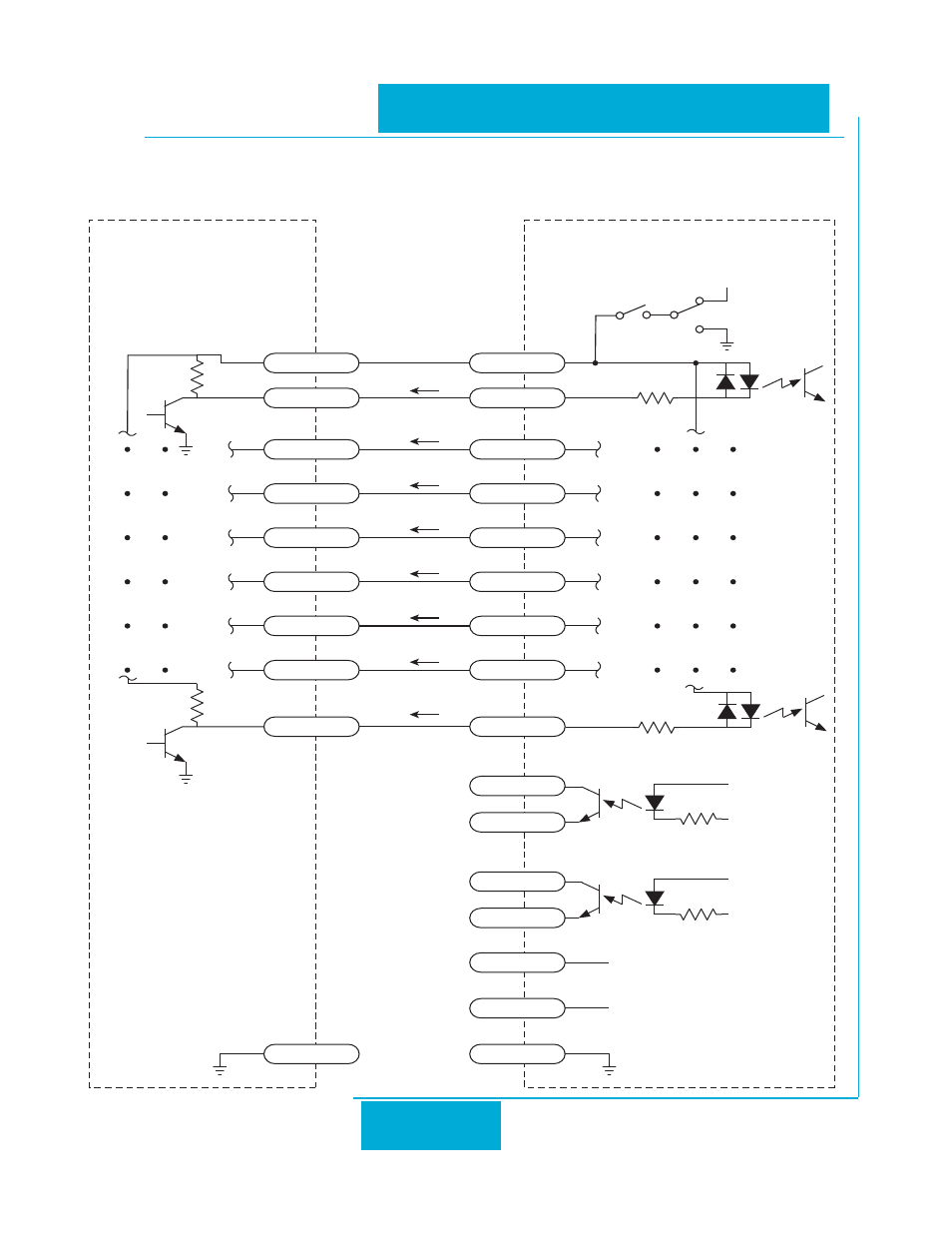
Connection diagrams:
Control wiring for sinking signals with an external power source.:
4.75K
+5V
inside drive
18
3
INCOM
CW/CCW
5
STMD
7
EN/RE
9
SPST
11
STP
13
M0
15
M1
17
M2
4.75K
+5V 50mA MAX
8
SPO+
10
SPO-
12
+5V
14
AIN
16
GND
4
FLT+
6
FLT-
+5V
GND
SW1 OFF
SW2 OFF
Advertising
This manual is related to the following products: