1 checks on receipt of the equipment, 2 introduction, 3 operating principle – CIRCUTOR LCL Series User Manual
Page 3: 1 how to select a lcl filter
------ LCL filters: Instructions Manual ----- Page 3
3
1 CHECKS ON RECEIPT OF THE EQUIPMENT.
Before installing and handling the equipment check that:
1) The equipment has not been damaged during delivery.
2) The equipment supplied is suitable for your requirements and is the type you ordered.
3) The operating voltage of the equipment supplied is suitable for your requirements.
4) Manuals for the equipment and for the regulator are supplied with the capacitor bank.
5) If any problem is noticed, please contact the commercial service department of CIRCUTOR S.A.
2 INTRODUCTION.
LCL filters are specially designed to reduce harmonics of current absorbed by power converters, with
a rectifier input stage. (Frequency converters for motors, UPS, etc.). Mainly, they are made of a
parallel-series combination of reactors and capacitors adapted to reduce the THD(I) of rectifiers. They
are specially designed
to reduce the THD(I) to values of approximately 8%, in order to comply with
IEC-61000-3.4 and IEEE-519 standards.
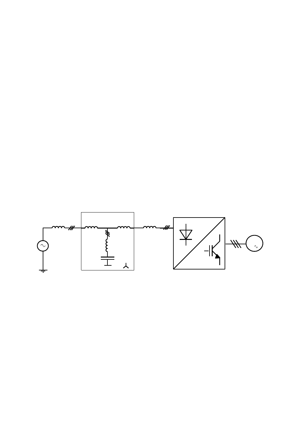
3 OPERATING PRINCIPLE.
The structure of LCL filters is as shown in the schematics below. The basic filter is designed with
L1,L2, L3 and C. In some cases reactor L4, is already placed in front of the converter. In such case L2
may be unnecessary
M
3
LCL FILTER
MAINS
IMPEDANCE
CONVERTER
L1
L2
L3
C
L4
Fig. 1.- LCL filters Structure
3.1 How to select a LCL filter?
LCL filters must be selected according to the current absorbed by the converter. In case of converters
with very low power rating, a unique LCL filter may be used to supply several converters, but only in
case the all start and stop at the same time. If several converters starting and stopping separately are
supplied by the same LCL filter, the system is not effective on filtering the harmonics. In such case an
individual LCL should be used for each converter.
ATTENTION: LCL filters may produce cos
overcompensation in case that the converter is absorbing
a current much lower than the rated current of the filter itself. This can be avoided by disconnecting
the parallel LC circuit when the current falls below a certain adjustable limit. An optional protection
circuit, consisting of a CMM-96-MD and a contactor, may be added to perform this function, if
requested in the order.