Signal inputs and link outputs, Input a/b and link a/b, Input digital aes/ebu and link – d&b D6 Hardware User Manual
Page 12
4.2.
Signal inputs and link outputs
NOTICE: To meet the EMC requirements only use shielded cabling and
properly fitted connectors.
4.2.1. INPUT A/B and LINK A/B
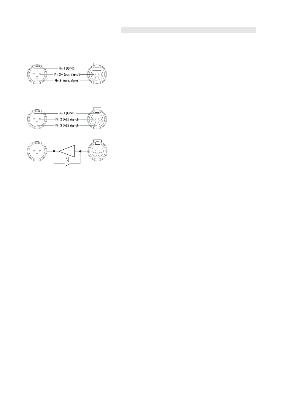
Fig. 3: Pin assignment ANALOG INPUT/LINK
A 3 pin female XLR input connector [9] is provided for channel A and B.
The inputs are electronically balanced.
Wired in parallel is a 3 pin male XLR input link connector [10] used to
feed the input signal on to the next device in the system signal chain.
4.2.2. INPUT DIGITAL AES/EBU and LINK
Fig. 4: Pin assignment DIGITAL INPUT/LINK
Digital INPUT
(AES/EBU)
Digital LINK
Power fail (Bypass)
Buffer
Fig. 5: Digital INPUT Bypass
A 3 pin female XLR AES/EBU [11] (AES 3) input and a 3 pin male XLR
LINK output [12] are provided.
The balanced input utilizes a transformer and is electrically isolated.
The digital LINK output may be used to feed a refreshed input signal to
the next device in the system signal chain. The signal shape (the rising
and trailing edges of the signal) and level are refreshed with an analog
signal amplifier.
A power fail relay is incorporated to prevent interruption of the signal
chain should there be a power failure. In this situation, the digital input
signal bypasses the analog buffer amplifier and is routed directly to the
LINK output.
D6 Amplifier, Hardware manual
(1.9 EN)
Page 12 of 24