Mains supply, Operating conditions – d&b D6 Hardware User Manual
Page 17
5.2.2. Mains supply
The table below indicates the number of devices per phase conductor
when full output power is required.
Mains supply
Number of devices
230 V / 16 A
Max. 4
115/100 V / 15 A
Max. 2
In the USA and Japan we recommend the use of mains leads with a
high cross section (min. 4 mm
2
/ AWG 12).
5.2.3. Operating conditions
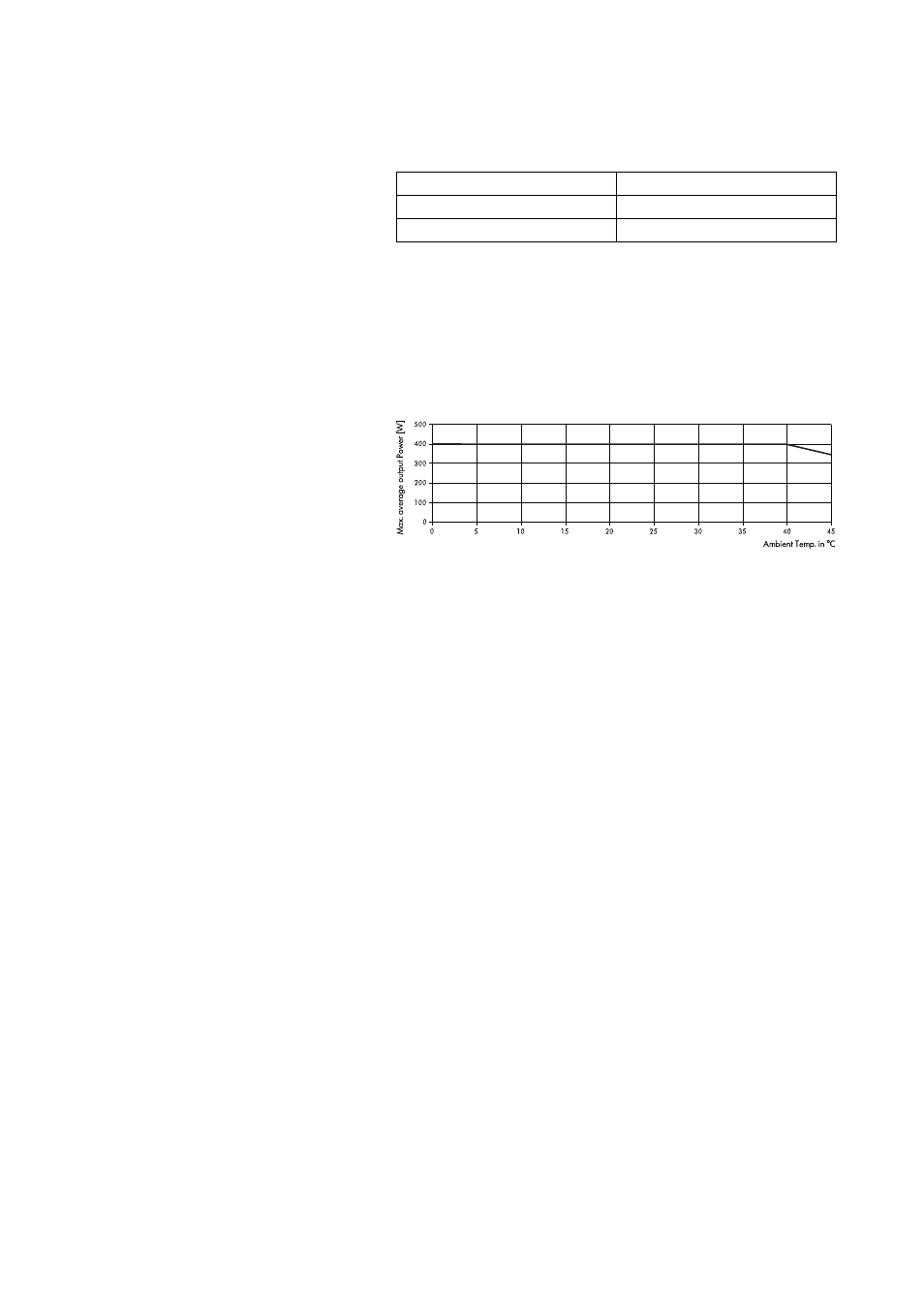
The following diagram shows the thermal operating range within which
the technical data will be maintained. The operation beyond this range
is possible for a short time and for thermal reasons this will trigger the
amplifier protection circuit into thermal overload.
Fig. 7: Average maximum total output power vs. ambient temperature
As explained in section 5.2.1, a worst case signal with a CF of 2.4 is
producing 1/3 of the rated sine output power or 200 watts at 4 ohms
per channel (400 watts total).
- The thermal management of the D6 is designed to deliver this power
for an unlimited amount of time within an ambient temperature of
up to 40° C (104° F).
-
With higher ambient temperatures, the maximum average
output power that can be delivered without entering thermal
protection, is reducing linearly as shown in the diagram above.
- When using the D6 at its
upper temperature limit of 45° C
(113° F), the maximum continuous output power is 340 watts total
or 170 watts per channel.
Again referring to section 5.2.1 - Tab. 4 - "D6 Power balance" - the unit
will work properly with e.g. 150 watts total when either
- running 4 ohms loads when the signal has a CF of 4.0
- or running 8 ohms loads if the worst case signal with a CF of 2.4
needs to be handled.
The maximum possible output power of 2 x 600 W at 4 ohms, which for
thermal reasons could only be supplied in short term (within minutes), is
unaffected by the ambient temperature.
D6 Amplifier, Hardware manual
(1.9 EN)
Page 17 of 24