D6 amplifier, D6 based systems, Block diagram – d&b D6 Hardware User Manual
Page 6
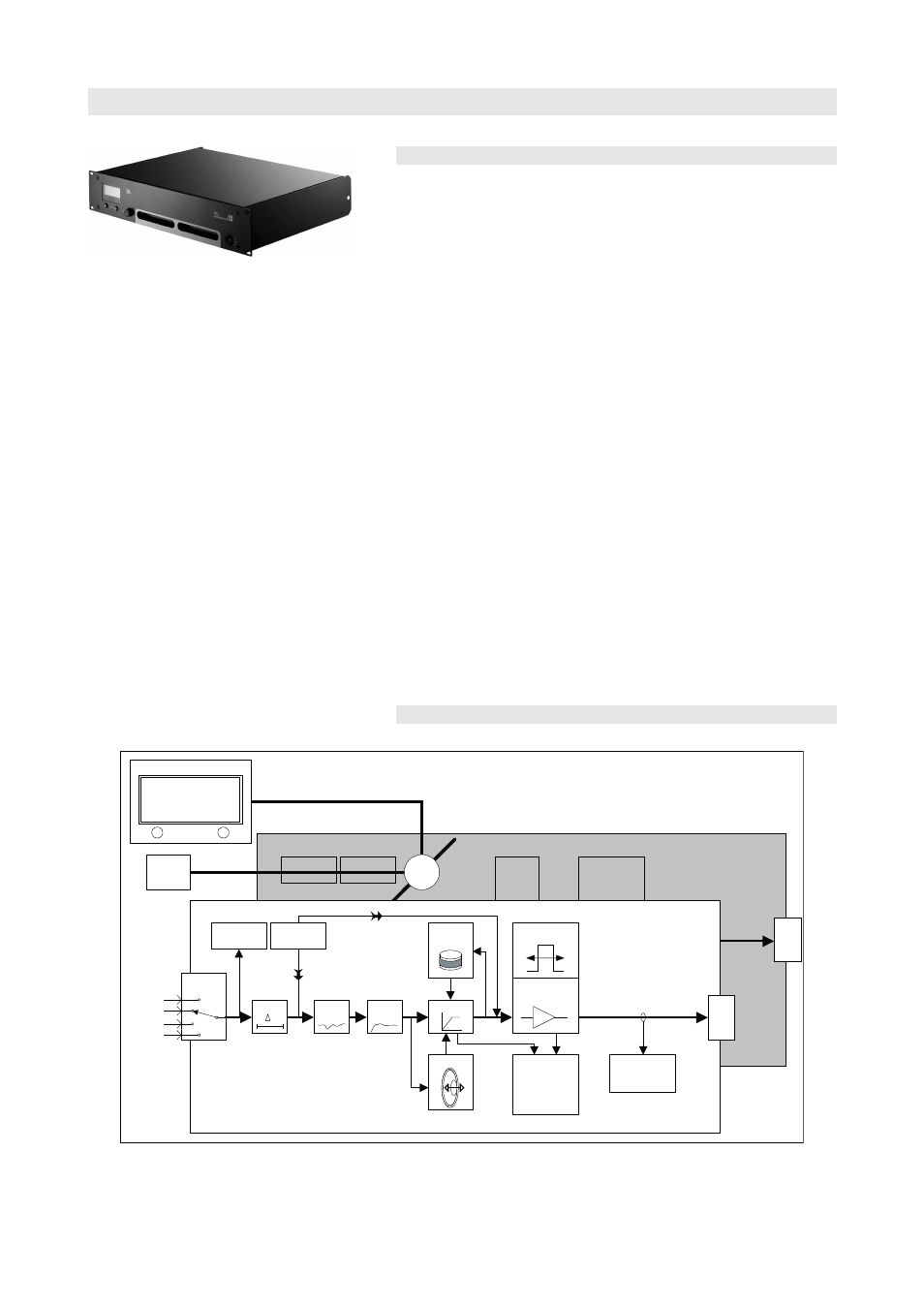
2. D6 Amplifier
Fig. 2: D6 Amplifier
2.1.
D6 based systems
The D6 Amplifier incorporates:
- universal voltage, switch mode power supply with active power
factor correction (PFC)
- two channel Class D power amplifier
- digital signal processors (DSP)
- comprehensive protection circuits
- controls and indicators
- analog and digital signal inputs and link outputs
- REMOTE and SERVICE interface
The level control on the front panel incorporates a digital rotary
encoder, which enables selection of all operating modes in conjunction
with a Liquid Crystal Display (LCD).
User definable equalization and delay functions are incorporated in
each channel of the D6. The 4-band parametric equalizer provides
optional Boost/Cut or Notch filtering and the signal delay capability
allows delay settings of up to 340 ms (= 100 m / 328 ft) to be applied
independently to either channel. A signal generator offering pink noise
or sine wave program is also incorporated for test and alignment
purposes. Each unit can be given a unique Device Name to simplify
identification and a password protected LOCK function is also
incorporated to inhibit unauthorized set up changes.
The D6 is housed in a 19" x 351 mm (13.8") 2 rack unit enclosure made
from steel.
2.2.
Block diagram
Power
amplifier
Input
routing
Analog A
Analog B
Digital A
Digital B
Signal
generator
sine wave or
pink noise for
acoustic tests
Input
monitoring
1+/2+
1-/2-
User
EQ
Delay
t
Dynamics
Coil temp.
t°
Power supply
Information
on headroom,
temperature,
power, mains
voltage
Excursion
Channel B
System
EQ/XO
pilot signals
for load
monitoring
Channel A
LC Display
Input
Ch A
Ch B
Link A>B
analog
> LINEAR
off
D6
remote
interface
uC
> LINEAR
1+/2+
1-/2-
Z analysis
for load
monitoring
I
D6 Amplifier, Hardware manual
(1.9 EN)
Page 6 of 24