Remote interface, Service – d&b D6 Hardware User Manual
Page 14
4.4.
REMOTE interface
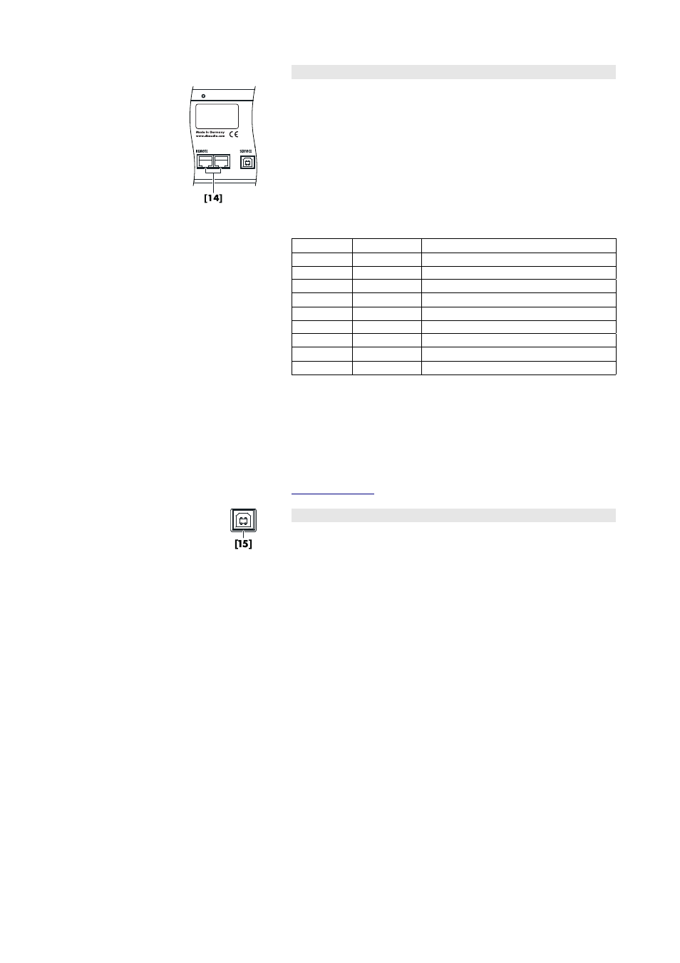
The D6 is fitted with a 2-wire serial remote control interface, (2 x RJ 45
[14]) carrying CAN-Bus signals.
All pins of both connectors are wired in parallel allowing either to be
used as the input or output. Where remote control networking conforms
to a "Bus or Ring topology" one connector is used for the incoming
signal and the second connector allows for direct connection to another
device (daisy chaining) or for terminating the last device at the end of a
CAN-Bus segment.
The reference ground of the CAN-Bus is hard wired to common ground
(protective earth) of the device.
Pin
Signal
Remark
1
-
2
-
3
-
4
CAN_H
"CAN high bus" signal (active high)
5
CAN_L
"CAN low bus" signal (active low)
6
-
7
-
8
-
Enclosure
GND
CAN Ground
The "CAN Ground" is routed via the cable shielding. Within the CAN-
Bus network, shielded cables and shielded RJ 45 connectors must be
used while the cable shielding must be connected to both sides of the
RJ 45 connector.
A detailed description of remote control via the d&b Remote network
(CAN-Bus) is given in the technical information TI 312 (d&b code
D5312.E.) which can be downloaded from the d&b website at
4.5.
SERVICE
The SERVICE interface [15] (USB type B connector) allows operating
software and loudspeaker configuration updates to be loaded into the
unit.
A detailed description of the update procedure is given in the D6
Software manual, which is also provided with the D6.
D6 Amplifier, Hardware manual
(1.9 EN)
Page 14 of 24