Sheet11, Drawing view37, Drawing view38 – Future Automation PLH User Manual
Page 14: Drawing view39, Detail view a (1.2 : 1), Drawing view41, Future automation plh, Electrical connections
Advertising
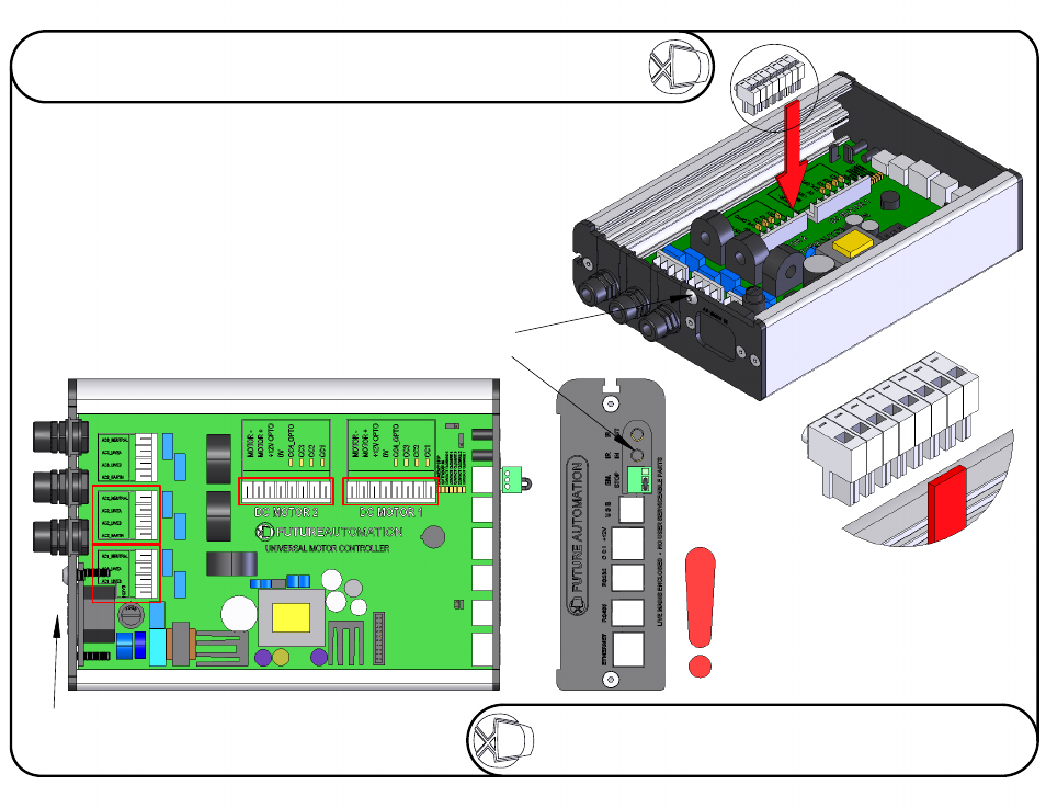
The PLH mechanism must be connected to the AC1, AC2,
DC1 and DC2 blocks of connections.
Connect the IEC Power Lead Here
A
Remove this screw to release the lid
It is VERY important that when all of the
electrical connections are made, the
connector blocks are connected in the
way shown above, with all the wires
coming directly out the top of the
connector blocks.
DETAIL A
SCALE 1.2 : 1
Connect the Infrared Sensor here
Electrical Connections
Sheet 13 of 17
ISSUE: 006
www.futureautomation.co.uk
FUTUREAUTOMATION
PLH
Plasma Lift Hinge Mechanism
Instruction Sheet
Advertising