Sheet5, Drawing view70, Drawing view72 – Future Automation PLH User Manual
Page 5: Drawing view73, Detail view b (2 : 3), Future automation plh, Stage 3
Advertising
B
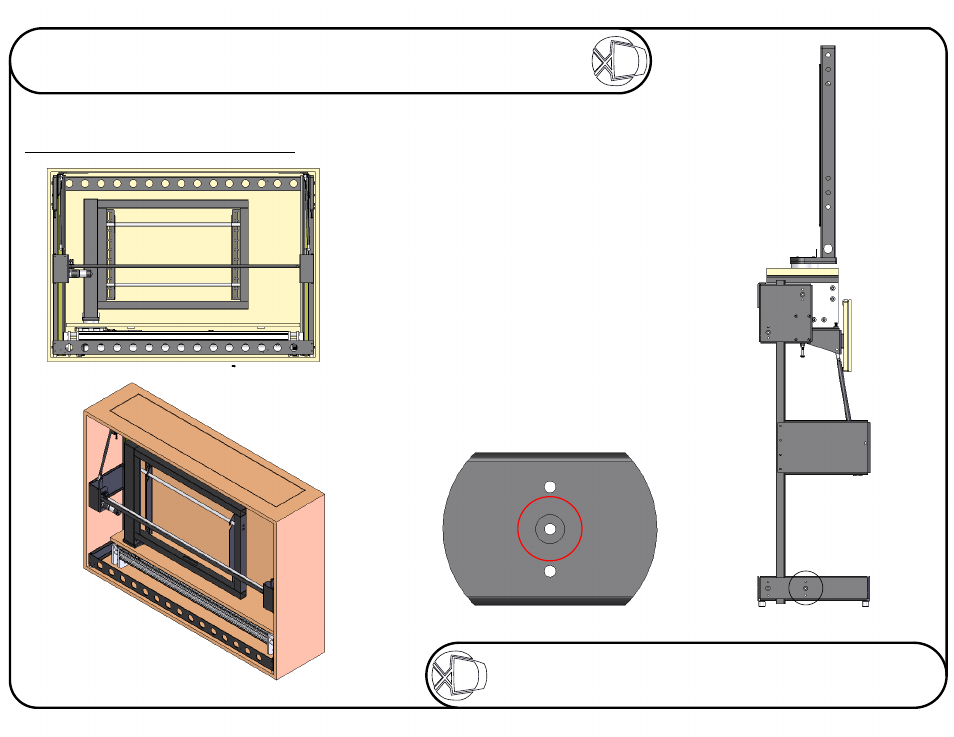
DETAIL B
SCALE 2 : 3
Stage 3
Fixing The Lift In The Cabinet
Place the mechanism within the cabinet.
Raise the beam to the top and guide the
base carefully through the opening in the top.
With the base properly located, use the 8
pointed screws supplied, 4 on each side,
to pin the mechanism in place, fixing its
position left and right. These 8 screws
should be screwed through the middle
hole of each of the clusters of 3,
shown below right.
With the lift fixed in position, use 8 wood
screws on each side to secure the
lift to the cabinet.
Sheet 4 of 17
ISSUE: 006
www.futureautomation.co.uk
FUTUREAUTOMATION
PLH
Plasma Lift Hinge Mechanism
Instruction Sheet
Advertising