Sheet8, Drawing view21, Drawing view22 – Future Automation PLH User Manual
Page 8: Drawing view23, Drawing view24, Drawing view25, Drawing view36, Drawing view86
1
2
3
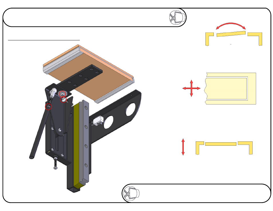
Adjusting The Flap-Up Position
Stage 6
1
By adjusting the white screw,
at each side of the lift, you can
adjust the tilt of the flap.
By winding the push rods on each side, you can
adjust the height of the flap in order to get it level
with the cabinet top. Be sure to lock the nut securely
once adjusted. Make sure the black plate does not
touch the inside of the cabinet. This can cause
strain on the motor, leading to failure.
3
2
CABINET TOP - SIDE VIEW
By loosening the M6 bolts on each
side under the flap, you can adjust
the position of the flap in the hole
in the cabinet top. Aim for a
3mm gap all round.
CABINET TOP - PLAN VIEW
CABINET TOP - SIDE VIEW
Sheet 7 of 17
ISSUE: 006
www.futureautomation.co.uk
FUTUREAUTOMATION
PLH
Plasma Lift Hinge Mechanism
Instruction Sheet