Sheet14, Drawing view42, Drawing view43 – Future Automation PLH User Manual
Page 15: Detail view b (1.5 : 1), Future automation plh, Contact closure, Plasma lift hinge mechanism instruction sheet
1
8
pins
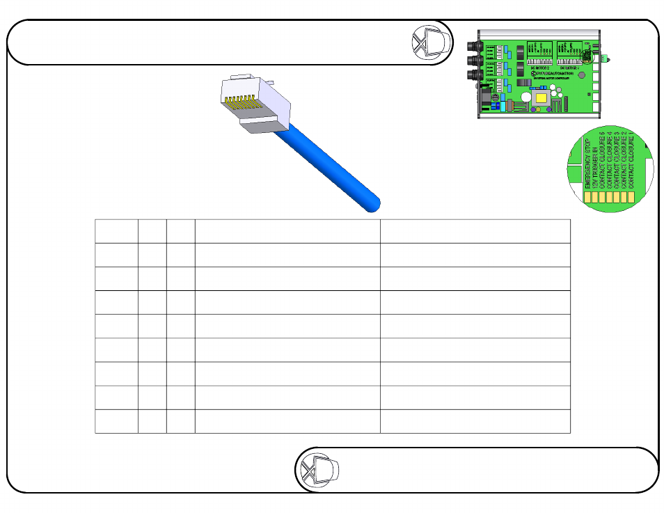
There are a number of LEDs
which will light up when the
corresponding contact closure
connections are shorted together.
A red LED will light up when the
emergency stop link is removed.
B
DETAIL B
SCALE 1.5 : 1
Sheet 14 of 17
ISSUE: 006
www.futureautomation.co.uk
FUTUREAUTOMATION
PLH
Plasma Lift Hinge Mechanism
Instruction Sheet
PIN
568
A
568
B
DESCRIPTION
ACTION
1
2
3
4
5
6
7
8
W/G
G
W/O
BL
W/BL
O
W/BR
BR
W/O
O
W/G
BL
W/BL
G
W/BR
BR
12V SUPPLY CURRENT LIMITED
12V TRIGGER
GROUND
DEVICE TOGGLE
DEVICE IN LATCHED
DEVICE STOP
DEVICE OUT
DEVICE IN
When 12V is attached, device will go OUT.
When 12V is removed, device will go IN.
Momentary short to ground will switch the
device between states of IN / OUT. CC5
Momentary short to ground,
will make screen go UP and HINGE. CC4
When shorted to ground,
stops device in current position. CC3
Momentary short to ground
will make screen go UP but NOT HINGE. CC2
Momentary short to ground
will make device go IN. CC1
Contact Closure
Use an RJ45 connector in the
CC1 socket on the control box
to operate via contact closure.