Sheet16, Drawing view45, Future automation plh – Future Automation PLH User Manual
Page 17: Operation details, Plasma lift hinge mechanism instruction sheet
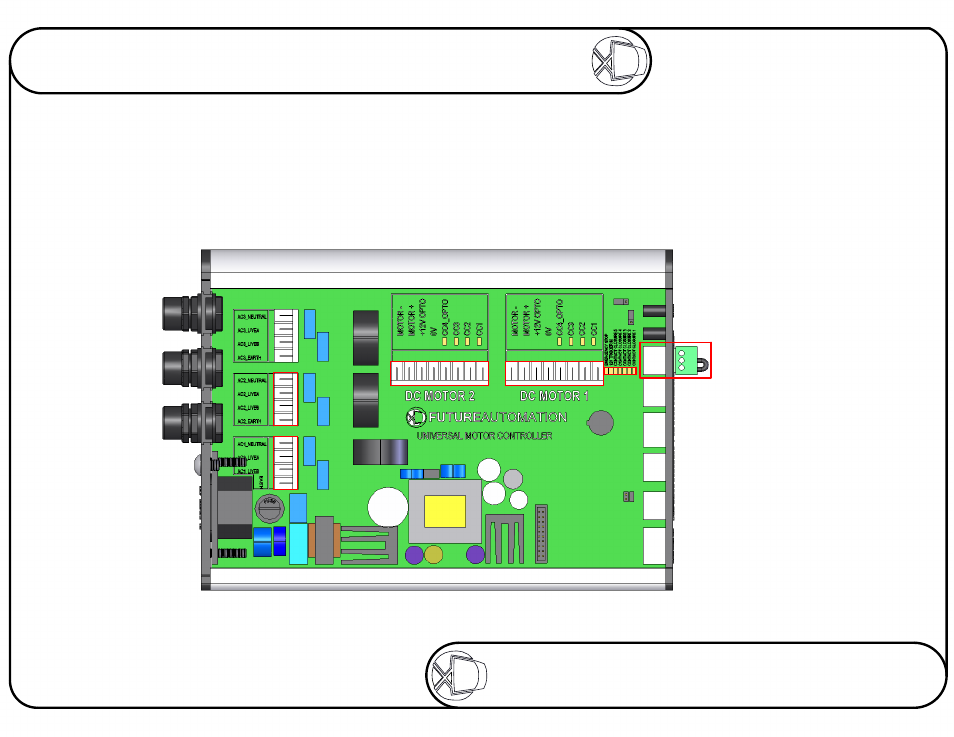
AC1
Gives an ouput of 240V(or 110V) to
control the Plasma Lift motor.
Outputs stay live for 60 seconds after
the OUT or IN functions are selected.
DC1
A low voltage connection for the
switches in the mechanism.
The four LEDs indicate the
state the mechanism is in.
CC1 Not Lit: Flap is OPEN
CC2 Not Lit: Flap is CLOSED
CC3 Not Lit: Beam is DOWN
CC4 Not Lit: Beam is UP
EMERGENCY STOP
This connection will stop all
functions of the mechanism
once broken / removed. Red
LED will also be on.
Contact Closure LEDs
To show the contact closure
operation is working correctly.
LEDs are on when connections
are shorted together.
DC2
Gives an ouput to
control the Plasma
Hinge motor.
DC2
A low voltage connection for the
switches in the mechanism.
The LEDs indicate the
state the mechanism is in.
CC1 Not Lit: Hinge is IN
CC2 Flashes: Hinge is OUT
CC1 & CC2 Lit: Home position
Operation Details
Sheet 16 of 17
ISSUE: 006
www.futureautomation.co.uk
FUTUREAUTOMATION
PLH
Plasma Lift Hinge Mechanism
Instruction Sheet