Holland Electronics DST-5000 User Manual
Page 11
9
3.2 Connect the receiver to one end of the CUT and one of the special
terminators to the other end of the CUT. The corresponding value of the
terminator will be displayed on the LCD display to identify the cable.
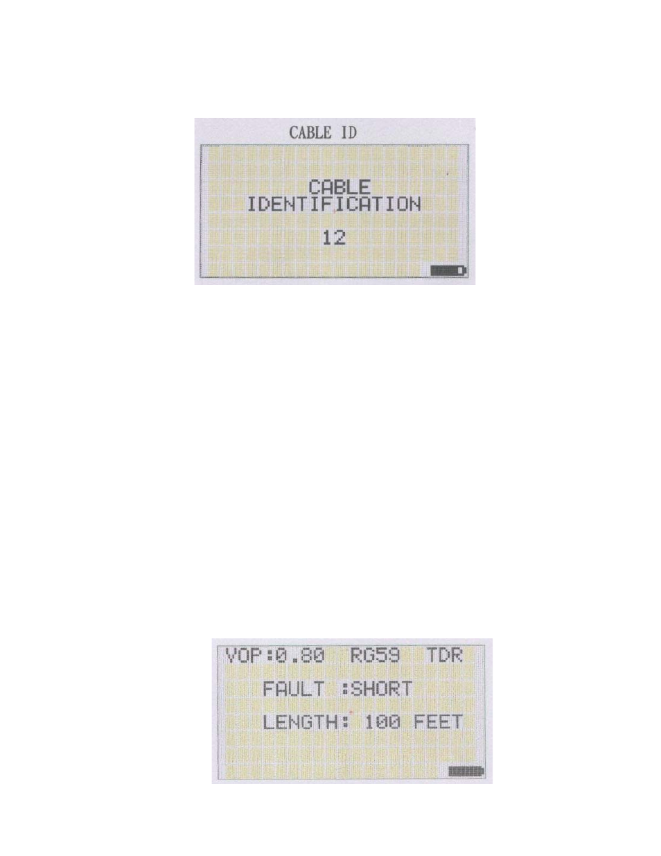
4. TDR Mode :
The TDR mode provides a method for determining if the cable under test has an
open circuit or a short circuit condition and approximately how far down the
cable from the receiver this fault exists.
The propagation constant (VOP) for standard industry cables (RG-6, RG-59,
RG-11, RG-58) is preprogrammed but the user can also connect a piece of
cable and perform a custom calibration before using the TDR for fault testing.
4.1 Press the MODE Key to select the TDR mode.
Use the following procedure when testing cable with a known VOP value:
4.1.1 Press the VOP Key to select the specific VOP value of the cable under test.
4.1.2 Connect one end of the CUT to the receiver input connector.
4.1.3 Press the TEST Key to test & display the type of cable fault (open/short)
and the distance (in feet) to the cable fault location.
The LCD will display as shown below: