KBC Networks MiniLink User Manual
Page 11
MINILINK® 5.8 TRANSMITTER – DIRECTIONAL / OMNI-DIRECTIONAL
MiniLink 5.8 GHz transmitters are available in two transmit configurations. A directional transmit path is ideal for frequency
isolation and fixed point-to-point applications, whereas omni-directional paths may be ideal for situations where orientation of the
transmitter is not fixed and transmit locations change frequently.
DIRECTIONAL TRANSMITTER (STANDARD STYLE)
A. FRONT VIEW
B. REAR VIEW
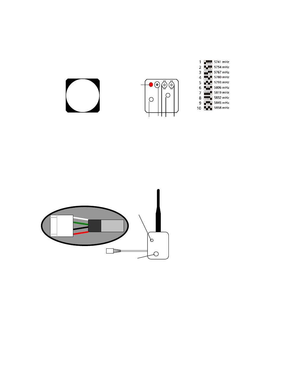
1.
CHANNEL SELECT
– 4-pin Dip switch
2.
POWER IN – Connect to power supply, connector 2.1 x 5.5 mm.
3.
VIDEO IN – Video input from camera source, BNC coaxial connection.
4.
AUDIO MODE SELECT – Select audio source, line level or microphone, +5 V electret supply.
5.
AUDIO IN – Audio input from audio source, BNC coaxial connection.
6.
LED – Indicates if unit has power applied.
OMNI-DIRECTIONAL TRANSMITTER (MODULAR STYLE)
A.
FRONT
VIEW
1. AUDIO MODE SELECT – Select audio source, line level or microphone, +5 V electret supply
2. VIDEO IN – Video input from camera source, 4 inch 24 AWG white wire.
3. AUDIO IN – Audio input from audio source, 4 inch 24 AWG green wire.
4. POWER IN
a. Ground – 4 inch 24 AWG black wire connected to 4-pin plug attached to power supply.
b.
Power – Red wire connected to 4 pin plug attached to power supply
5. CHANNEL SELECT – 4-position dipswitch.
- 9 -
1 2 3 4 5
6
Match the dipswitches to the setting
on the label for the desired channel.
Any numbers visible on the switch
itself are not used. The white squares
indicate the switch location.
5
1
2
3
4a
4b