Escriptions and, Pecifications, Minilink – KBC Networks MiniLink User Manual
Page 6: 8 receiver description
D
ESCRIPTIONS AND
S
PECIFICATIONS
MINILINK
®
5.8 RECEIVER DESCRIPTION
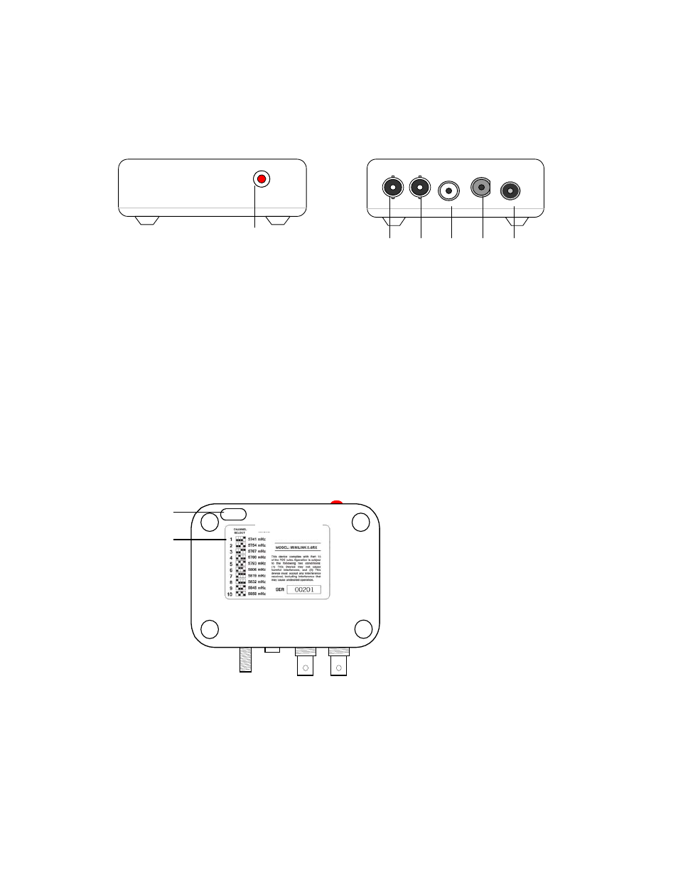
FRONT AND REAR VIEWS
1. LED INDICATOR
Indicates power is on when illuminated
2. POWER INPUT
12VDC 440 mA. Power supply included.
3. RF INPUT
“F” connector, connection to LNB via RG6 coaxial cable.
4. AUDIO OUTPUT
Mono audio output to video monitor or DVR, use either right or left channel
5. VIDEO OUT
Supply filtered, clamped video output to video monitor or VCR.
6. VIDEO OUT
Supply filtered, clamped video output to video monitor or VCR.
BOTTOM VIEW
1. CHANNEL SELECT DIPSWITCH
Dip switch for selection channels 1 – 10. (Receiver and transmitter channels must
match). The Receiver is factory set to Channel 10
2. CHANNEL SELECT LABEL
Shows dip switch settings for channels 1 – 10.
- 4 -
6 5 4 3 2
1
1
2