5 power connections, 6 fault alarm contact – KBC Networks ESUL5P User Manual
Page 8
Ethernet Switch User Manual
Manual-ESUL5P_Series_HW-Rev1112
Copyright © KBC Networks Ltd.
Page 8 of 14
www.kbcnetworks.com
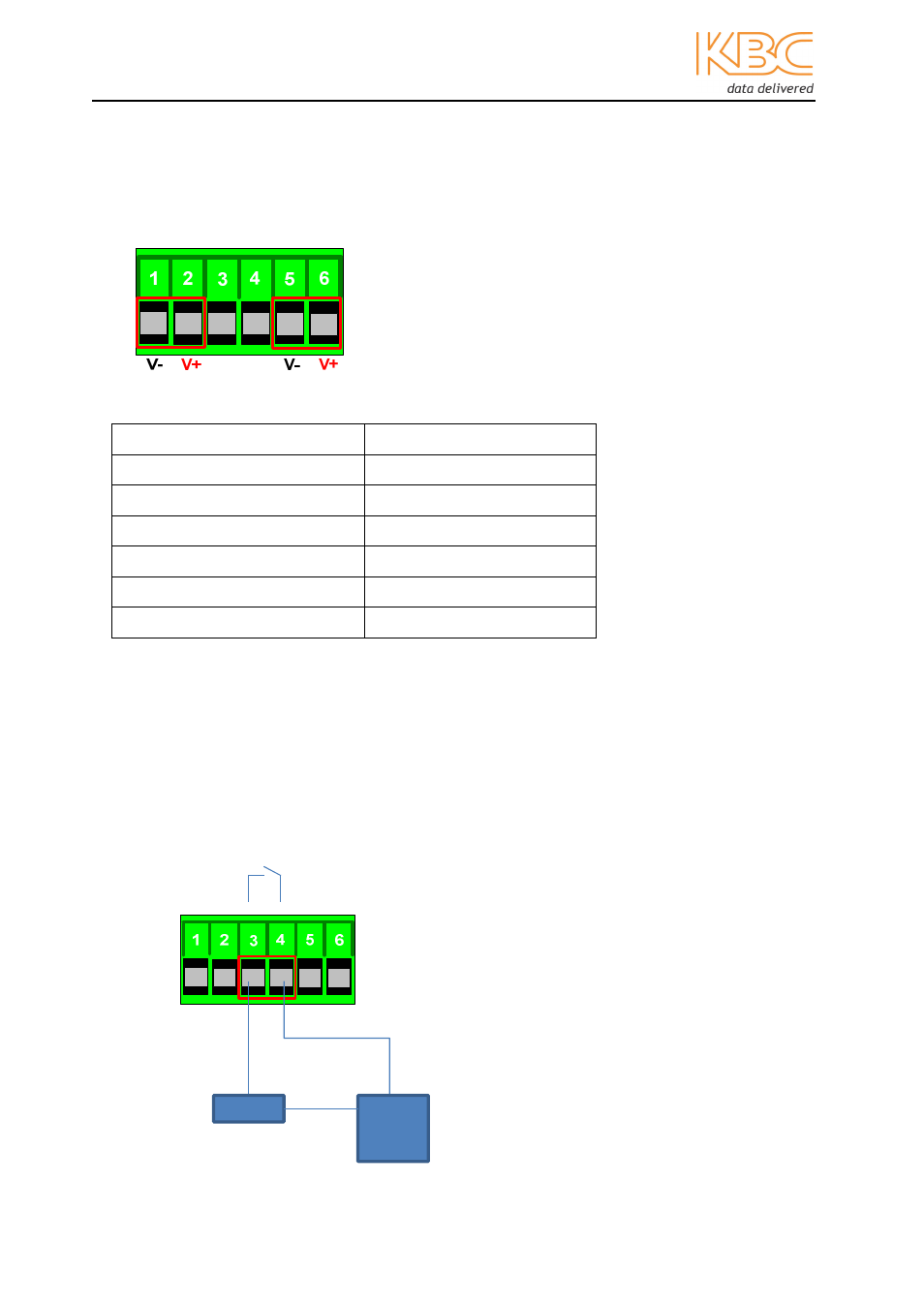
2.5 Power Connections
A 6 pin, power terminal block should be used to connect the power cable to the unit.
Figure 2.1 Power connections
Contact number
Connections
1
Power 2 -
2
Power 2 +
3
Fault alarm contact
4
Fault alarm contact
5
Power 1 -
6
Power 1 +
Note:
If only using one power source, connect pin 1 to pin 5 and pin 2 to pin 6
otherwise the Power Fail LED will be lit.
2.6 Fault Alarm Contact
The fault alarm contacts are in the middle of the 6 pin, screw block terminal on pins 3 &
4. The relay is rated at 1A@24Vdc and an open circuit will occur if a power failure is
detected.
Fig 2.2 Fault Alarm Contacts
Load
External
power
24Vdc, 1A resistance
P-Fail