4 coaxial cable connection, 5 ethernet cable connection, 6 power connections – KBC Networks EE2CL User Manual
Page 12
Extended Ethernet User Manual
Manual-EE2CL_Series-Rev1304.docx
Copyright © KBC Networks Ltd. 2013
Page 12 of 19
www.kbcnetworks.com
2.4 Coaxial Cable Connection
Connect the unit’s BNC socket to the coaxial cable. When a physical link over coaxial
cable is established and the units are powered up, the green BNC LED will light to show
that the unit has detected another unit and then flash to indicate there is link activity.
See section 2.7 for complete details of LED status.
2.5 Ethernet Cable Connection
The RJ45 port is adaptive and supports auto MDI/MDI-X connection. It can be connected
by straight through or cross-over type Cat5 or Cat 6 cables. The green RJ45 LED will
light to indicate a link connection and flash to show when data traffic is being passed.
See section 2.7 for complete details of LED status.
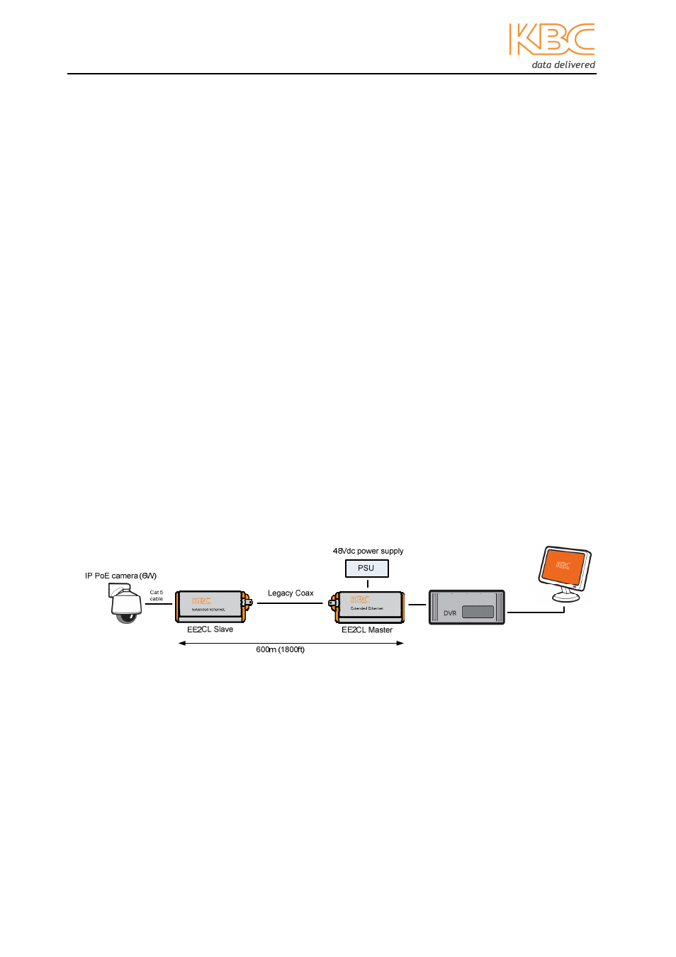
2.6 Power Connections
This EE2CL unit must be powered by the +48Vdc, 1.25A PoE power supply, this is
supplied with the unit and is connected using a 2.1mm barrel connector.
Note:
For higher power or longer distance applications please contact KBC Networks.
Depending on power requirements and cable distances, power for both the Master and
Slave EE2CL units and the IP cameras can be supplied from the PSU located at the
Master EE2CL unit.