Grounding – NeoPro Tahoe-Veo User Manual
Page 10
10
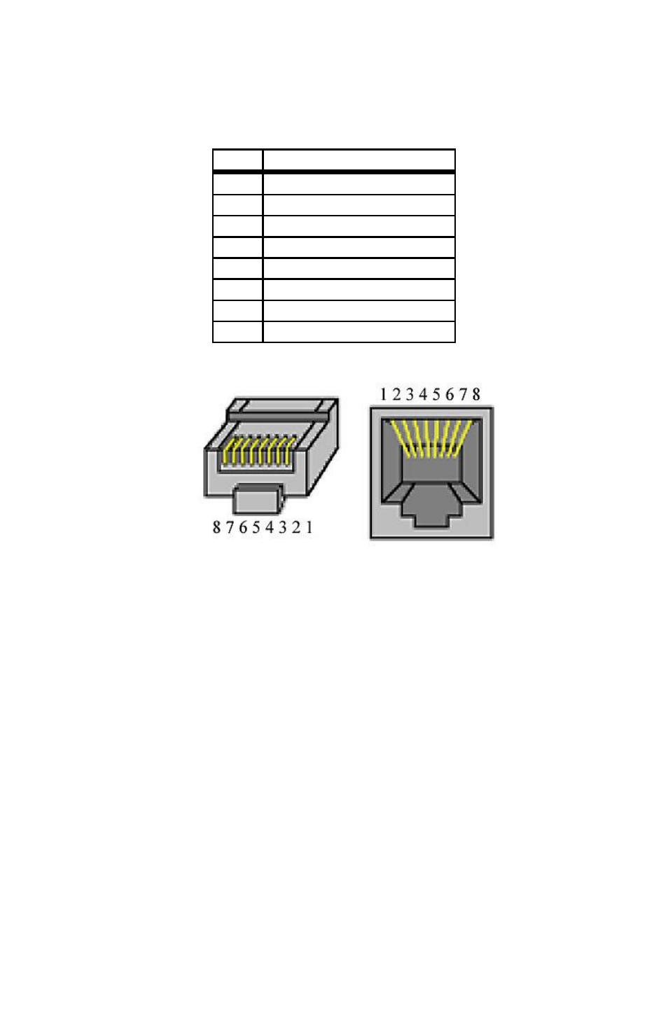
Before connecting CAT5 cables, make sure the wire pairs are terminated as
shown in Figure 1 and Table 1 below. The common standards known as 568A
and 568B are electrically equivalent and can both be used so long as both ends
are terminated the same way.
Pin
Video Signal Pairs
1
+Y
2
-Y
3
+Pb
4
24 Vdc
5
24 Vdc return
6
-Pb
7
+Pr
8
-Pr
Table 1 - RJ45 connector signal names
Figure 1 - Identifying pin 1 on the RJ45 connector
The center pair of the RJ45 connector carries 24VDC to the active Cat5 receiver
units, and is required. However if using the passive Cat5 receiver units, the
center pair can be utilized for other signals such as IR. When doing this, make
sure that both ends of the cable have the center pair removed before connecting
to the switch system and the Cat5 receiver.
The matrix system is designed to drive only one Cat5 receiver per output port.
Do no split the Cat5 signal to additional Cat5 receivers.
Grounding
In most structures, modern three wire outlets will power all the equipment and
provide a safety ground. However as systems are upgraded over time, and add-
on work might not be completed to the National Electric Code (NEC), the
ground system can become compromised. For your A/V system, this may not
only affect performance, but may also leave the equipment susceptible to surge
damage.
Your Cat5 receivers have basic surge suppression circuits built in, so for best
performance and protection, either the display or the Cat5 receiver should be