Nife 100 and nife 101 system components, Top view – NEXCOM NIFE 100 User Manual
Page 23
Advertising
Copyright © 2015 NEXCOM International Co., Ltd. All Rights Reserved.
9
NIFE 100/101 User Manual
Chapter 2: Jumpers and Connectors
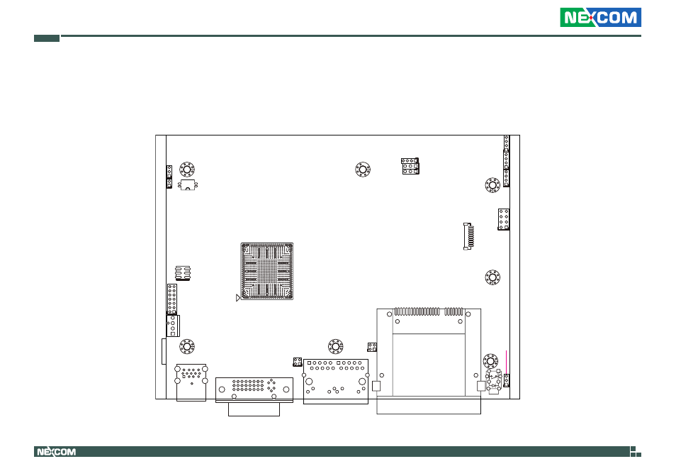
NIFE 100 and NIFE 101 System Components
The NIFE 100 and NIFE 101 system are made up of a NIFB 105 motherboard and an I/O daughterboard. This chapter lists the location and pinout assignment
of the jumpers and connectors on each component.
BJ
BH
BG
BA BC BE
AR AU AW
AL AN
AC AE AG AJ
W AA
R U
N
G J L
A C E
53
51
49
47
45
43
41
39
37
35
33
31
29
27
25
23
21
19
17
15
13
11
9
7
5
3
1
4
1
1
3
1
3
4
1
4
1
4
1
7
1
8
2
1
10
S1
P17
3
1
4
2
3
1
4
2
B9
B10
B2
B1
A9
A10
A2
A1
8
16
24
9
1
17
5
4
1
10
13
9
1
5
1
6
2
1
2
3
1
3
1
14
13
2
1
H7
USB 3.0/ USB 2.0
LAN1/ LAN2
CFAST
PWR
BUTTON
U22
JP11
JP10
DVI-I
SW1
JFW1
JP9
CN7
JP4
CN9
CN10
LAN1
CN8
SW2
JP8
J1
JP12
JP6
JP2
JP1
JP3
JP5
JP7
Locations of the Jumpers and Connectors for NIFB 105
Top View
Advertising