Spot-1 callouts - external power supply – Oxmoor SPOT-1 User Manual
Page 5
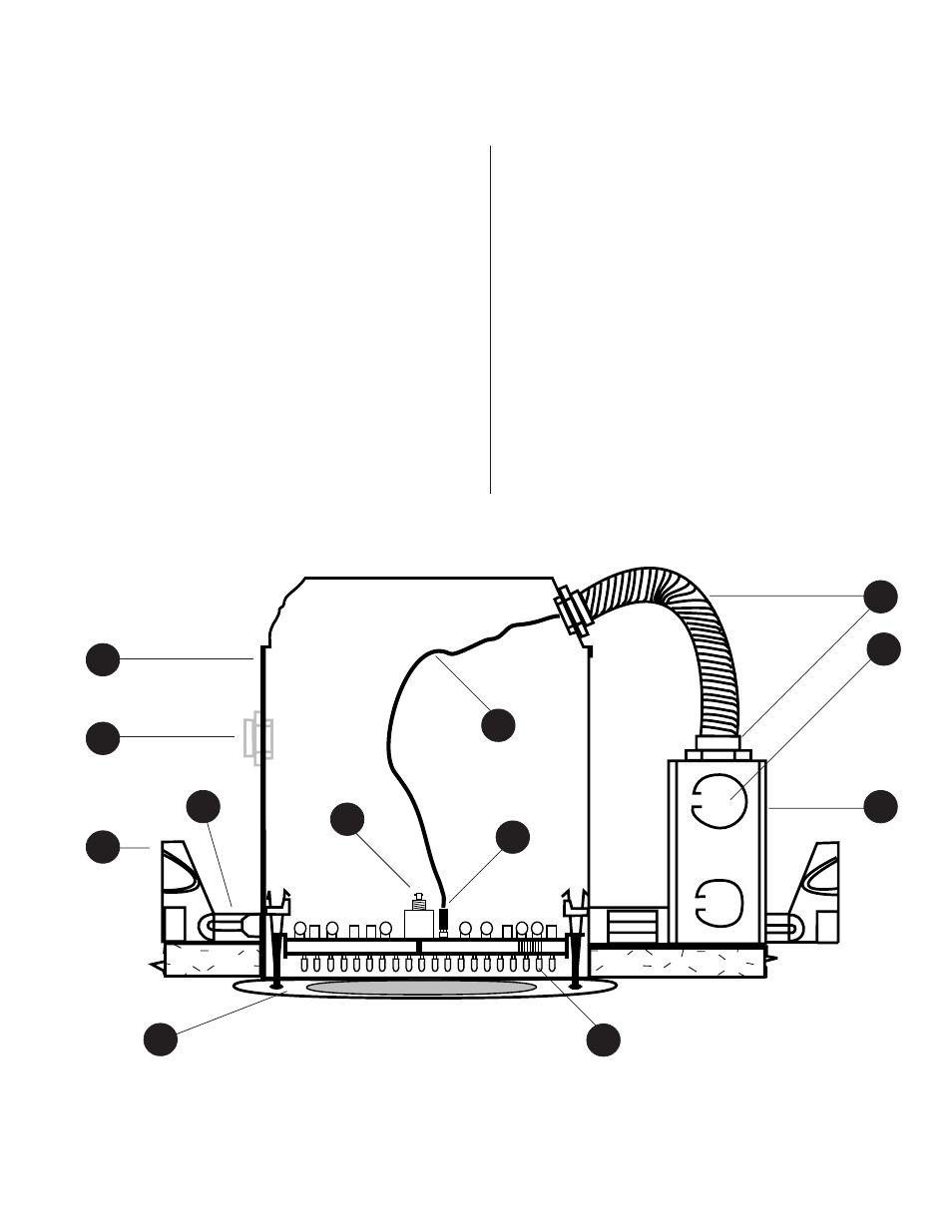
Figure 1.1: SPOT-1e Infrared Emitter With External Power Supply
Page 3
SPOT-1 CALLOUTS - EXTERNAL POWER SUPPLY
1. HOUSING
– Die-stamped, 20 gauge, cold rolled steel with
white powder coat finish.
2. RF CONDUIT KNOCKOUT
– 1/2” uniform opening for RF
cable entry. NOTE: Requires a gasketed EMT air tight com-
pression connector or gland nut when used in a plenum
ceiling.
3. PLASTER FRAME
– Housing adjusts in plaster frame
1-3/8” to accommodate different ceiling thicknesses.
4. BAR HANGERS
– Fully adjustable “nail-less” bar hang-
ers fit between 24” joists and span 24” T-bars. Hanger bars
are scored for reducing for 12” joist spans. Housing may
be positioned at any point along length of fully extended
bar hangers.
5. TRIM RING
– White metal trim ring with glass lens.
6. RF INPUT CONNECTOR
– BNC-style RF input connector.
Input impedance 25 k ohms at 95 kHz.
10
5
3
2
1
4
6
7
9
7. DC POWER CONNECTION
– 3-pin header connector. Cen-
ter Pin Positive with both outside pins negative. NOTE:
Requires 24V DC supply at 1.25 amps, voltage regulation
±
5 % with a maximum peak to peak ripple of 240 mV.
8. DC POWER CABLE
– 2-conductor cable, terminates in
junction box.
9. DIODE ARRAY
– 72-diode array designed to cover small
“spot” areas of approximately 314 to 2,800 square feet.
10. JUNCTION BOX
– Fully gasketed for Plenum listing. UL
listed for through branch circuit wiring.
11. POWER KNOCKOUTS
– Positioned to accommodate
straight conduit runs. All conduit knockouts are uniform
1/2” size with pry out slots.
12. CONDUIT FITTINGS
– Plenum approved flexible metal-
lic tubing and gasketed connectors.
11
12
8