Spot-1 emitter set-up, Spot-1 set-up overview, Factory settings are – Oxmoor SPOT-1 User Manual
Page 6: Jumper configuration, Jumper p5, Jumper p6, Jumper p7, Caution
Page 4
SPOT-1 EMITTER SET-UP
SPOT-1 SET-UP OVERVIEW
When driving SPOT-1 with a carrier frequency operating
at 76.8 kHz, 95 kHz, or 250 kHz, SPOT-1 can be configured
to automatically turn off when no carrier frequency is
detected. SPOT-1 will turn on again when it detects the
appropriate carrier frequency. This feature conserves
energy and extends the life of the 72 emitter diodes.
If the transmitter is operating at a carrier frequency other
than 76.8 kHz, 95 kHz, or 250 kHz, jumper P5 has to be
set to the OFF position. This causes SPOT-1 to remain on
until its power is removed. If P5 is set to the OFF position,
jumpers P6 and P7 are removed from the circuit and can
be left in any position.
FACTORY SETTINGS ARE:
P5 - Carrier Detection On
P6 - 95 kHz Selected
P7 - 250 kHz Selected
JUMPER CONFIGURATION
(Refer to Figure 2.0)
Jumper P5
If the RF modulator is operating at 76.8 kHz, 95 kHz, or
250 kHz, move jumper P5 to the ON position. If the RF
modulator is operating at any other frequency, jumper P5
must be in the OFF position.
Jumper P6
If the RF modulator is operating at 76.8 kHz, move jumper
P6 to the 76.8 kHz position and P7 to the OFF position. If
the RF modulator is operating at 95 kHz, move jumper P6
to the 95 kHz position and P7 to the OFF position.
Jumper P7
If the RF modulator is operating at 250 kHz, move jumper
P7 to the 250 kHz position. P6 can be positioned either to
76.8 kHz or 95 kHz when operating at 250 kHz.
CAUTION:
If the 250 kHz frequency is not used, be sure
to position the 250 kHz detector in the OFF position!
USER CONFIGURATION CHART
Modulation
Jumper
Frequency
Position
P5
P5
P5
P5
P5
P6
P6
P6
P6
P6
P7
P7
P7
P7
P7
76.8 kHz
95 kHz
250 kHz
All Others
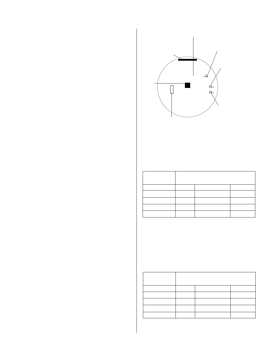
Figure 2.0: Factory Set-Up Jumper Configuration
P5 – ON Selected
P5
P6
P7
F1
P2
P7 – 250 kHz Selected
P6 – 95 kHz Selected
1-1/4 Amp Line Fuse
RF Jack
12-Pin Header Connection
For Emitter Driver Board
SPOT-1 Emitter Driver Board
ON
ON
ON
ON
ON
OFF
OFF
OFF
OFF
OFF
76.8 kHz
76.8 kHz
76.8 kHz
76.8 kHz
76.8 kHz
95 kHz
95 kHz
95 kHz
95 kHz
95 kHz
Off
Off
Off
Off
Off
250 kHz
250 kHz
250 kHz
250 kHz
250 kHz
CARRIER DETECTION CONFIGURATION CHART
Modulation
Jumper
Frequency Position
P5
P5
P5
P5
P5
P6
P6
P6
P6
P6
P7
P7
P7
P7
P7
76.8 kHz
On
76.8
Off
95 kHz
On
95
Off
250 kHz
On
X
250
All Others
Off
X
X
X = Either Position
BOLD & ITALIC = Factory Settings