Vectronics VEC-830K User Manual
Page 9
VEC-830K Instruction manual
Single Side-Band Filter
STEP-BY-STEP ASSEMBLY
Before assembling your kit, please take time to read and understand the VEC kit
warranty printed on the inside cover of this manual. Also, read through the
assembly instructions to make sure the kit does not exceed your skill level. Once
you begin construction, your kit will be non-returnable. Finally, if you haven't
already done so, please verify that all parts listed in the inventory are included.
If anything is missing or broken, refer to the warranty instructions for
replacing missing or damaged parts.
Note that part designators, such as R1, C3, etc., appear on a silk-screened legend
on the component-mounting side of the printed circuit board. This corresponds
with the parts placement page in the manual. All parts will be inserted on the
silk-screen side of the board.
If you have last-minute questions about what you need to build your kit, please
refer back to the section titled "Tools and Supplies". If you're ready to begin
now, here we go! The directions use two sets of check boxes. Check one when a
step is complete and use the other for double-checking your work before
operation.
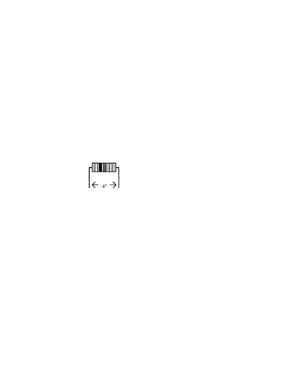
1. Locate resistor R1.
This is a 300K ohm resistor (orange-black-
yellow-gold).
Carefully bend the leads close to the resistor body to form right-angles (see
following diagram).
2. Insert R1 into its mounting holes so the resistor body rests against the board.
Solder in place and trim the leads.
3. Locate resistor R2.
This is a 100K ohm resistor (brown-black-
yellow-gold).
4.
Insert R2 into its mounting holes so the resistor body rests against the board.
Solder in place and trim the leads.
5. Locate resistor R3.
This is a 100K ohm resistor (brown-blackyellow-
gold).
6. Locate resistor R4.
This is a 150K ohm resistor (brown-greenyellow-
gold).