Ta x, Operating your ds8000 – XTA DS8000/D User Manual
Page 11
Page 11
DS8000 Operator’s Manual
ta
x
Operating your DS8000:
Operating your DS8000:
Operating your DS8000:
Operating your DS8000:
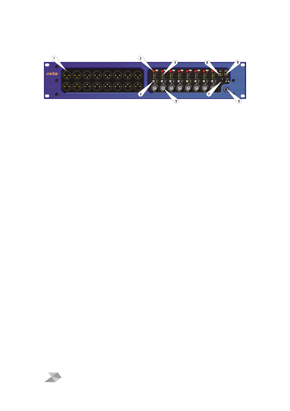
Front Panel Controls and Sockets
POWER
SUPPLY
O/B
SPLIT
EXT.
-6
-6
-6
-6
-6
-6
-6
-6
0
0
0
0
0
0
0
0
6
6
6
6
6
6
6
6
12
12
12
12
12
12
12
12
18
18
18
18
18
18
18
18
24
24
24
24
24
24
24
24
30
30
30
30
30
30
30
30
36
36
36
36
36
36
36
36
42
42
42
42
42
42
42
42
GAIN
SOLO
+18
0
-24
+12
GAIN
SOLO
+18
0
-24
+12
GAIN
SOLO
+18
0
-24
+12
GAIN
SOLO
+18
0
-24
+12
GAIN
SOLO
+18
0
-24
+12
GAIN
SOLO
+18
0
-24
+12
GAIN
SOLO
+18
0
-24
+12
GAIN
SOLO
+18
0
-24
+12
INT.
1
1-4
5-8
5
10
LEVEL
DS8000 AUDIO DISTRIBUTION SYSTEM
TRANSFORMER
BALANCED
OUTPUTS
1
3
2
4
5
6
7
8
1
3
2
4
5
6
7
8
H
EA
DPHO
NE
S
1: Transformer balanced outputs: These are post gain control and are galvanically isolated.
Pin 1 on the XLR sockets is NOT connected by default, but this can be changed if required —
please see notes on page 17 for more information.
2: 48V phantom power switch and indicator: Press this to send 48V phantom power to this
input socket. Note that the indicator will illuminate even if the rear “PANEL SAFE” switch has
been pressed. Please check this switch if no phantom power seems to be present.
3: Solo listen switch and indicator: Press this to send the respective input channel signal to
the solo bus, and to the headphone amp (on this unit). Solo switching is additive so more than
one may be enabled at once and they will mix on the bus. It’s good practice to make sure you
turn solos off even if you unplug your headphones, especially when you have the solo bus
connected between units, as a stray solo left on can waste hours looking for the odd signal
you can hear in your headphones if it is on a different but connected unit! Note that if an “O/B
Split” is enabled then the solo switch on a “slave” channel will STILL route the respective
input to the solo bus.
4: Channel output meter: This meter shows output level respective to the electronic MON
and FOH outputs. It is affected by the gain control.
5: Gain control: This rotary switch allows the input gain for the respective channel to be
adjusted and has a wide enough range to cater for microphone level signals (and amplify
them to line level) as well as padding down “very hot” line level signals if required.
6: O/B Split indicators: These LEDs show the status of the rear panel “O/B Split” switches —
if illuminated, then the respective input (1 or 5) is routed to multiple channels’ outputs (for
input 1 this is all outputs on channels 1-4, and for input 5, this is all outputs on channels 5-8).
For more information on this feature please see page 14.
7: Headphone volume: This control adjusts the level fed to the headphones — remember if all
solo switches are OFF, nothing will be heard so it’s advisable to turn this down before
“soloing” any channel as it may suddenly be very loud!
8: Power supply status indicators: Under normal circumstances, only the green INT.
(Internal) LED should be illuminated, even when two units are interconnected via the external
supply sockets on the rear. Should one unit’s power fail, the other will supply power to both,
and the red EXT. (External) LED will illuminate instead on the “failed” unit.
9: Headphone socket: connect headphones to monitor the solo bus. The headphones
channels are driven separately but are mono.