Ta x – XTA DS8000/D User Manual
Page 16
DS8000 Operator’s Manual
Page 16
ta
x
Internal Adjustments of your DS8000:
Internal Adjustments of your DS8000:
Internal Adjustments of your DS8000:
Internal Adjustments of your DS8000:
User options
The following options are adjustable by you, the user, without invalidating the warranty.
Please observe the safety warnings before you undertake any of these adjustments!
Grounding pin 1 on front panel transformer balanced outputs
By default, the front panel transformer isolated outputs do not have pin 1 on the XLR sockets
connected. This is the most usual way to operate transformer balanced outputs — the
grounding use for a shield is derived from the “remote” device, to retain galvanic isolation
and prevent possible hum loops or potential differences across various grounds causing
other problems.
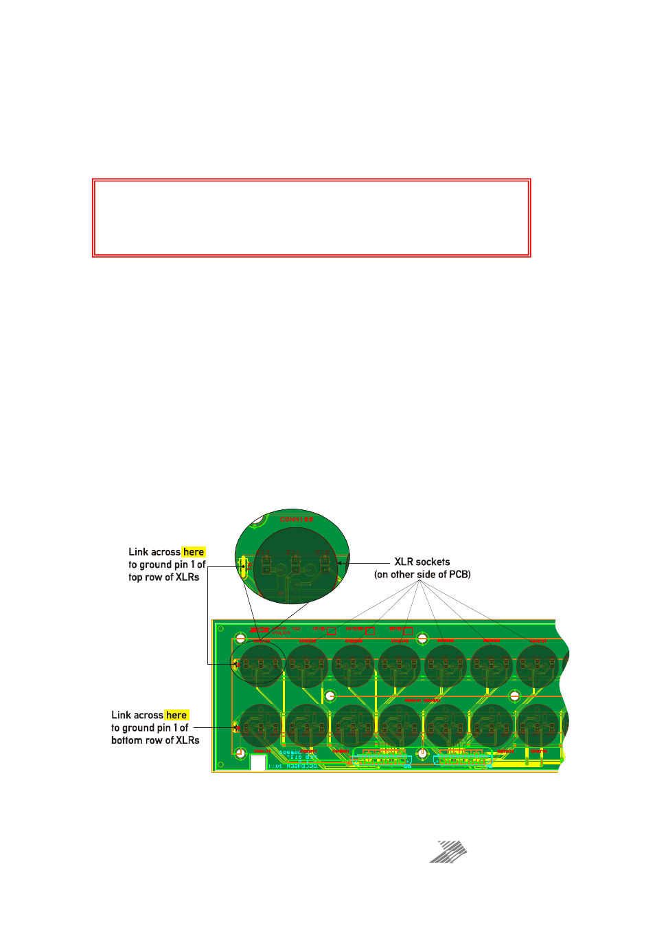
However, under certain circumstances, it may be preferable to connect this ground. This is
achieved by adding links on the rear of the
front panel XLR PCB
. There are two links — one to
connect the entire top row to ground, and one for the bottom row.
The diagram below shows the rear of the board, when viewed from behind (front panel
facing
away from
you) with the link positions highlighted.
SAFETY WARNINGS
Disconnect the unit from the mains supply before removing the cover!
Lethal voltages in excess of the mains input voltage are present — do not remove the
protective cover from the internal power supply!